background image

English-5

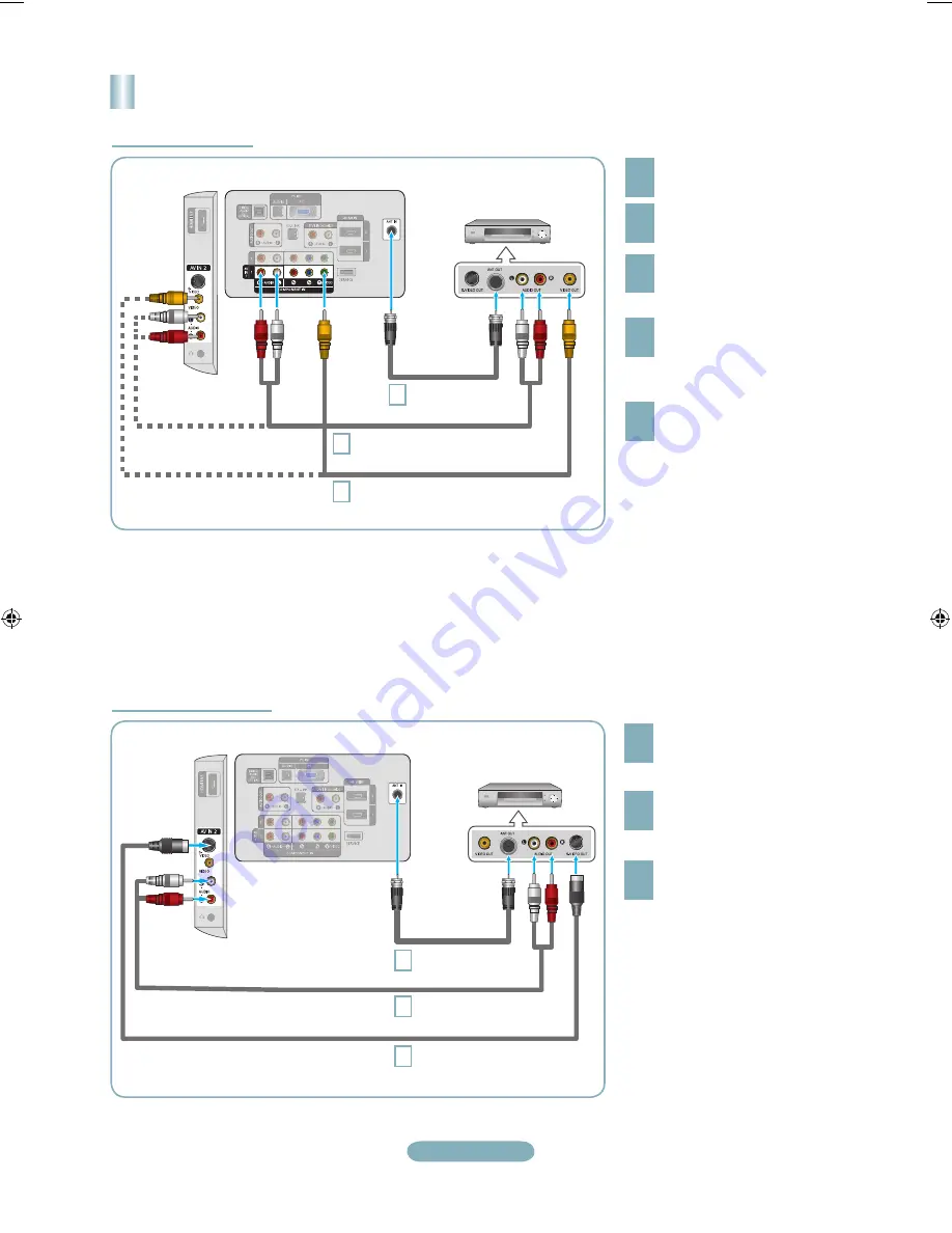
Connecting a VCR


2
3

4

If you have a “mono” (non-stereo) VCR, 

use a Yconnector (not supplied) to 

connect to the right and left audio input 

jacks of the TV. Alternatively, connect 

the cable to the “R” jack. If your VCR is 

stereo, you must connect two cables.

Follow the instructions in “Viewing a VCR or Camcorder Tape” to view your VCR tape.

Each VCR has a different back panel configuration.
When connecting a VCR, match the color of the connection terminal to the cable.
When connecting to AV IN 1, the color of the AV IN 1 [Y/VIDEO] jack (Green) does not match the color of the video cable 

(Yellow).

TV Rear Panel

3

RF Cable (Not supplied)

5

Audio Cable (Not supplied)

VCR Rear Panel

4

Video Cable (Not supplied)

5

Connect the cable or antenna 

to the ANT IN terminal on the 

back of the VCR.
Connect an RF Cable between 

the ANT OUT terminal on the 

VCR and the ANT IN terminal 

on the TV.

Connect a Video Cable 

between the VIDEO OUT jack 

on the VCR and the AV IN 1 

[Y/VIDEO] or AV IN 2 [VIDEO] 

jack on the TV.

Unplug the cable or antenna 

from the back of the TV.

Connect Audio Cables between 

the AUDIO OUT jacks on the 

VCR and the AV IN 1 (or AV IN 2) 

[R-AUDIO-L] jacks on the TV.

Video Connection

S-Video Connection

TV Rear Panel

3

S-Video Cable (Not supplied)

RF Cable (Not supplied)

VCR Rear Panel

2

Connect Audio Cables between 

the AUDIO OUT jacks on the 

VCR and the AV IN 2  

[R-AUDIO-L] jacks on the TV.

3

Connect an S-Video Cable 

between the S-VIDEO OUT jack 

on the VCR and the AV IN 2  

[S-VIDEO] jack on the TV.

To begin, follow steps 1–3 in 

the previous section to connect 

the antenna or cable to your 

VCR and your TV.

An S-Video cable may be included 

with a VCR. (If not, check your local 

electronics store.)

Each VCR has a different back 

panel configuration.
When connecting a VCR, match 

the color of the connection 

terminal to the cable.

2

Audio Cable (Not supplied)

TV Side Panel

TV Side Panel

BN68-01393E-Eng.indd   5

2008-03-20   ¿ÀÈÄ 1:51:06

Summary of Contents for LN32A540P2D

Page 1: ...this product please visit www samsung com global register LN32A540P2D Rear Panel Side Panel Jacks 1 AUDIO OUT 2 DIGITAL AUDIO OUT OPTICAL 3 PC IN PC AUDIO 4 HDMI IN 1 2 3 DVI IN HDMI2 R AUDIO L 1 ANT IN 6 AV IN 2 7 HEADPHONE 8 SERVICE 9 POWER INPUT 0 COMPONENT IN 1 2 AV IN 1 EX LINK KENSINGTON LOCK Audio Output Performance Comparison OPTICAL Digital AUDIO Analog Best Normal Video Input Performance...

Page 2: ...d sound modes for sports cinema and games Use these buttons in the DMA and Anynet modes This remote can be used to control recording on Samsung recorders with the Anynet feature SOURCE Press to display and select the available video sources PRE CH Tunes to the previous channel CH CH Press to change channels MENU Displays the main on screen menu CC Controls the caption decoder RETURN Returns to the...

Page 3: ...le cable The difference between HDMI and DVI is that the HDMI device is smaller in size and has the HDCP High Bandwidth Digital Copy Protection coding feature installed Connect an HDMI Cable between the HDMI IN 1 2 or 3 jack on the TV and the HDMI jack on the DVD Player or Cable Box Satellite receiver Set Top Box DVD Player or Cable Box Satellite receiver Set Top Box Each DVD Player or Cable Box S...

Page 4: ...e component video and audio connections For example if connecting a Component video cable to COMPONENT IN 1 connect the audio cable to COMPONENT IN 1 also Each DVD Player or Cable Box Satellite receiver Set Top Box has a different back panel configuration When connecting a DVD Player or Cable Box Satellite receiver Set Top Box match the color of the connection terminal to the cable Connecting a Ca...

Page 5: ...e VCR and the ANT IN terminal on the TV Connect a Video Cable between the VIDEO OUT jack on the VCR and the AV IN 1 Y VIDEO or AV IN 2 VIDEO jack on the TV Unplug the cable or antenna from the back of the TV Connect Audio Cables between the AUDIO OUT jacks on the VCR and the AV IN 1 or AV IN 2 R AUDIO L jacks on the TV Video Connection S Video Connection TV Rear Panel 3 S Video Cable Not supplied ...

Page 6: ...l sound to the Home theater receiver When the source is a digital component such as a DVD and is connected to the TV via HDMI only 2 channel sound will be heard from the Home Theater receiver If you want to hear 5 1 channel audio connect the DIGITAL AUDIO OUT OPTICAL jack on the DVD player or Cable Satellite Box directly to an Amplifier or Home Theater not the TV Connecting an Amplifier DVD Home T...

Page 7: ...configuration When connecting a PC match the color of the connection terminal to the cable When using an HDMI DVI cable connection you must use the HDMI IN 2 jack Using the D Sub Cable 1 Connect a HDMI DVI cable between the HDMI IN 2 jack on the TV and the PC output jack on your computer 2 Connect a 3 5 mm Stereo mini plug 2RCA Cable between the DVI IN HDMI2 R AUDIO L jack on the TV and the Audio ...

Page 8: ...ress the ENTER button If you have Digital cable TV select the cable system signal source for both Analog and Digital Viewing the Menus 5 The TV begins memorizing all available stations After all the available channels are stored it start to remove scrambled channels Press the EXIT button to exit To Stop the Auto Program Function Press the MENU button while the Auto Program function is being execut...

Page 9: ... button Picture Mode Dynamic Selects the picture for high definition in a bright room Standard Selects the picture for the optimum display in a normal environment Movie Selects the picture for viewing movies in a dark room 3 Press the or button to decrease or increase the value of a particular item Press the ENTER button Press the EXIT button to exit When you make changes to Backlight Contrast Bri...

Page 10: ...cted to the TV set Use this button to choose an input source that you would like to watch Available signal sources TV AV1 AV2 S Video Component1 Component2 PC HDMI1 HDMI2 HDMI3 You can choose only those external devices that are connected to the TV Source List TV Move Enter Return TV AV1 AV2 S Video Component1 Component2 PC more ...

Page 11: ...reen Make sure the broadcast you re receiving is High Definition HD HD channels sometimes broadcast Standard Definition SD programming which can cause black bars Set your cable satellite box to stretch or widescreen mode to eliminate the bars Picture has a Red Green or Pink tint Make sure the Component cables are connected to the correct jacks Closed Captioning not working If you are using a Cable...

Page 12: ...rvicio de Atención al Cliente Country Customer Care Center Web Site Address CANADA 1 800 SAMSUNG 726 7864 www samsung com ca Samsung Electronics Canada Inc Customer Service 55 Standish Court Mississauga Ontario L5R 4B2 Canada Samsung Electronique Canada Inc Service à la Clientèle 55 Standish Court Mississauga Ontario L5R 4B2 Canada U S A 1 800 SAMSUNG 726 7864 www samsung com Samsung Electronics A...

Reviews: