background image

Plug & Play

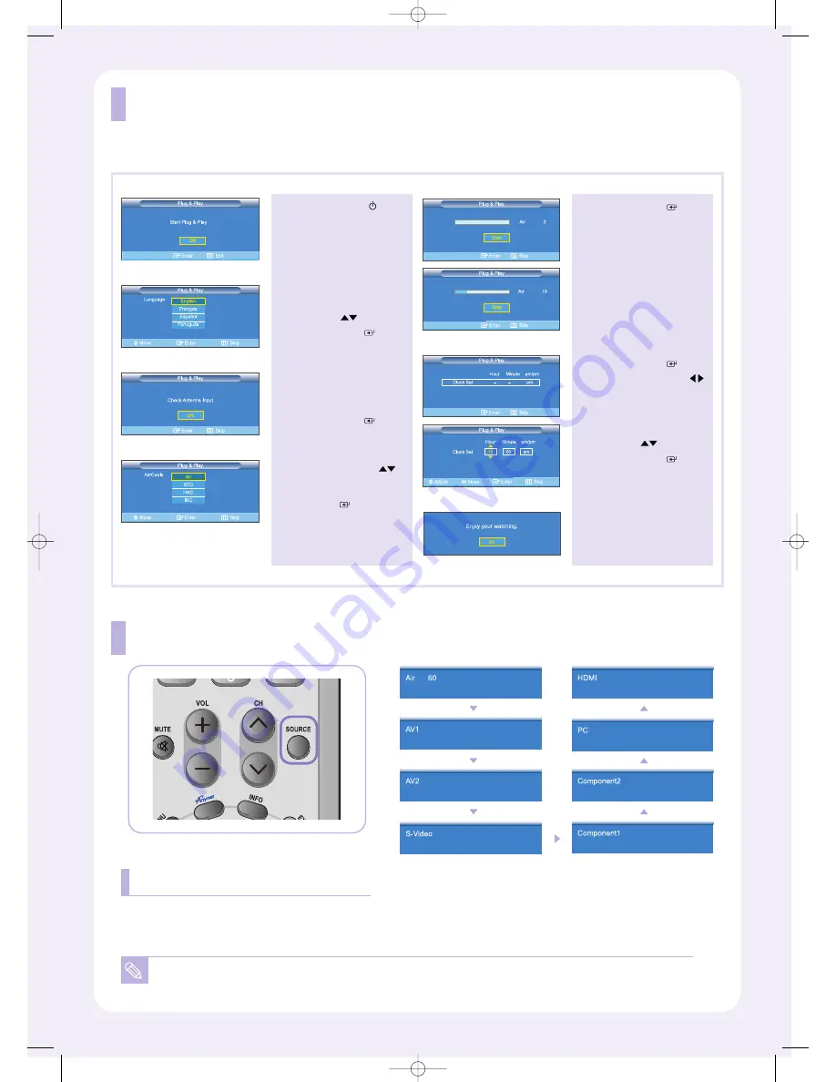
When the TV is initially powered on, several basic customer settings proceed automatically and subsequently.

1

Press the

POWER

button

on the remote control.

The message
“Start Plug & Play” is
displayed with “OK” selected.

2

Select the appropriate
language by pressing the

UP/DOWN

buttons.

Press the 

ENTER

button

to confirm your choice.

4

Press the 

UP/DOWN

buttons to select “Air”, “STD”,
“HRC”, or “IRC”, then press
the 

ENTER

button.

5

Press the

ENTER

button

to select “Start”.

The TV will begin memorizing
all of the available channels.

6

Press the 

ENTER

button.

Press the 

LEFT/RIGHT

buttons to move to the
“Hour”, “Minute” or “am/pm”.

Set the “Hour”, “Minute” or
“am/pm” by pressing the

UP/DOWN

buttons.

Press the 

ENTER

button.

7

The message
“Enjoy your watching.”
is displayed.

3

The message
“Check Antenna Input” is
displayed with “OK” selected.

Press the 

ENTER

button.

To Select the Source

You can select the TV mode or an input source connected to the TV set.
Use this button to choose an input source that you would like to watch.

You can only select a source if it is connected to your TV.

Press the SOURCE button on the remote control

BN68-00515V-00.qxd  1/11/05 4:10 PM  Page 6

Summary of Contents for LN-R268W

Page 1: ... BN68 00515V 00 Remote Control BN59 00455A Batteries AAA x 2 Anynet Cable BN39 00518B Owner s Instructions Power Cord 3903 000085 Anynet AV Owner s Instructions Cover Bottom BN68 01674A RF Cable AA39 00039A Stand 23 26 BN96 01727A 32 BN96 01733A Cleaning Cloth Stand Screw 6002 001294 x 4 M4 X L16 BN68 00515V 00 qxd 1 11 05 4 10 PM Page 1 ...

Page 2: ...a input terminal keep the copper wire portion of the RF cable straight to avoid bending it For more detailed antenna cable TV connections refer to the owner s Instructions Installing the stand 1 Lower the TV set in the direction of the arrow and fix the stand 2 Use the four screws to tightly fix the stand 2 1 BN68 00515V 00 qxd 1 11 05 4 10 PM Page 2 ...

Page 3: ...ption TV Rear Panel RF Cable VCR Rear Panel 1 2 4 3 1 2 3 4 1 2 4 3 Connecting a VCR Connect the cable TV or antenna to the ANT IN terminal on the back of the VCR Connect an RF cable between the ANT OUT terminal on the VCR and the ANT IN terminal on the TV Connect an audio cable between the AUDIO OUT jacks on the VCR and the AV IN R AUDIO L jacks on the TV Connect a video cable between the VIDEO O...

Page 4: ... and the AUDIO OUT jacks on the DVD player For an explanation of Component video see your DVD player owner s manual Component Cable Option Audio Cable Option TV Rear Panel DVD Player Rear Panel Component Cable Option Audio Cable Option TV Rear Panel Set Top Box Rear Panel 1 2 Connect a component cable between the COMPONENT IN 1 or COMPONENT IN 2 PR PB Y jacks on the TV and the COMPONENT Y PB PR ja...

Page 5: ...he AUDIO OUT jacks on the DVD player Set top box 1 2 HDMI Cable Option TV Rear Panel DVD Player Rear Panel 1 Connect an HDMI cable between the HDMI DVI connector on the TV and the HDMI connector on the DVD player Set top box 1 Connecting a PC 2 1 Connect a PC video cable D Sub between PC IN PC connector on the TV and the PC output connector on your computer Connect a PC audio cable between PC IN A...

Page 6: ...will begin memorizing all of the available channels 6 Press the ENTER button Press the LEFT RIGHT buttons to move to the Hour Minute or am pm Set the Hour Minute or am pm by pressing the UP DOWN buttons Press the ENTER button 7 The message Enjoy your watching is displayed 3 The message Check Antenna Input is displayed with OK selected Press the ENTER button To Select the Source You can select the ...

Page 7: ...e The left hand side of the screen shows the original image VCR DVD Functions Only Anynet mode Rewind Stop Play Pause Fast Forward CAPTION Controls the caption decoder PIP Picture in Picture ON OFF SLEEP Press to select a time for the TV to turn off automatically PRE CH Tunes to the previous channel CH and CH Channel UP Down Press CH or CH to change channels VOL and VOL Press to increase or decrea...

Page 8: ...n the output source i e STB with a digital signal Not Supported Mode message Check the maximum resolution and the frequency of the Video Adapter Compare these values with the data in the Display Modes Remote control malfunctions Replace the remote control batteries Clean the upper edge of the remote control transmission window Check the battery terminals No sound or sound is too low at maximum vol...

Reviews: