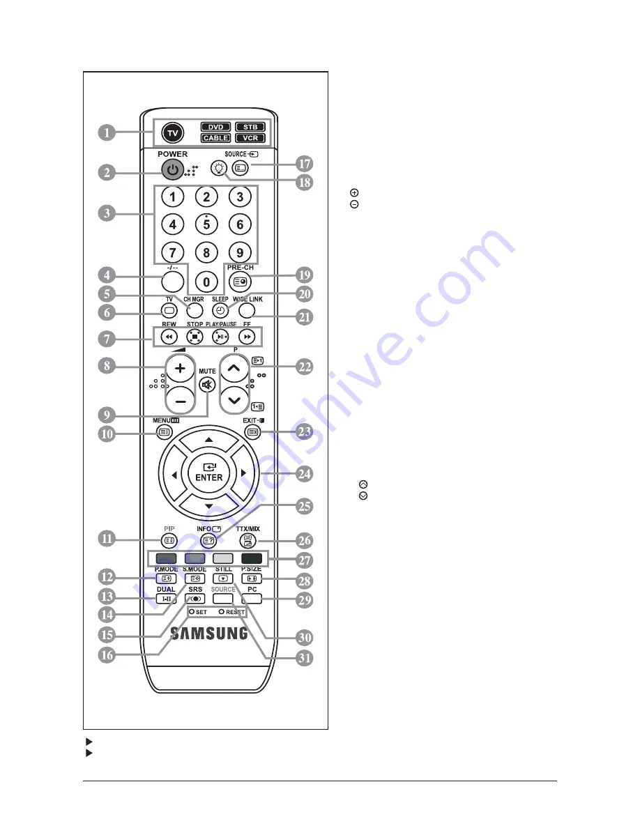
The performance of the remote control may be affected by bright light.
This is a special remote contro for the visually impaired, and has Braille points on the Power, Channel
and Volume buttons.
10 Operating Instructions and Installation
10-4
10-3 Remote Control
1. Selects a target device to be controlled by the
Samsung remote control (TV, DVD, STB,
CABLE, VCR)
2. Television Standby button
3. Number buttons for direct channel access
4. One/Two-digit channel selection
5. It display "Channel Manager" on the screen.
6. Selects the TV mode directly
7. VCR/DVD Functions
Rewind, Stop, Play/Pause,
Fast/Forward
8.
Volume increase
Volume decrease
9. Temporary sound switch-off
10. Menu display and change confirmation
11. Picture-In-Picture On / Off
12. Picture effect selection
13. Sound effect selection
14. Sound mode selection
15. SRS TSXT selection
16. SET : Adjusts 5 separate devices - TV,
DVD, STB, CABLE, or VCR.
RESET : When your remote does not work,
change the batteries and press the "RESET"
button for 2-3 seconds before use.
17. Available source selection
18. When pressing this button, a number of
buttons on the remote control (e.g. Selects a
target device, volume, channel and MUTE
buttons) light up for a few seconds and then
turn off to save power.
This function is to conveniently use the
remote control at night or when dark.
19. Previous channel
20. Automatic Power-off
21. This function enables you to load saved photo
(JPEG) and audio files (MP3) and to view or
play them on the TV.
22. P : Next channel
P : Previous channel
23. Exit the OSD
24. Control the cursor in the menu
25. Use to see information on the current broadcast
28. Picture size selection
29. Selects the PC mode directly
30. Picture freeze
31. Input source selection
Tteletext Functions
6. Exit from the teletext display
10. Teletext index
11. Teletext hold
12. Teletext size selection
14. Teletext store
17. Teletext mode selection (LIST/FLOF)
19. Teletext sub page
22. P : Teletext next page
P : Teletext previous page
23. Teletext cancel
25. Teletext reveal
26. Alternately select Teletext, Double, or Mix.
27. Fastext topic selection
Summary of Contents for LE32N71B
Page 3: ...Contents ...
Page 4: ...Contents ...
Page 17: ...Memo 10 Operating Instructions and Installation 10 6 ...
Page 23: ...11 Disassembly and Reassembly 11 6 Memo ...
Page 27: ...Memo 1 Precautions 1 4 ...
Page 35: ...14 Reference Infomation 14 8 14 3 2 Supported Modes 1 ...
Page 36: ...14 Reference Infomation 14 9 14 3 3 Supported Modes 2 ...
Page 37: ...14 Reference Infomation 14 10 14 3 4 Supported Modes 3 ...
Page 47: ...3 Alignments and Adjustments 3 4 ...
Page 48: ...3 Alignments and Adjustments 3 5 ...
Page 53: ...Memo 3 Alignments and Adjustments 3 10 ...
Page 57: ...4 Troubleshooting 4 4 WAVEFORMS 1 R G B Output Signal of IC500 ...
Page 59: ...4 Troubleshooting 4 6 2 Digital Output Data of IC500 3 Signal of HDMI Data ...
Page 61: ...4 Troubleshooting 4 8 WAVEFORMS 4 Tuner_CVBS Output Signal 3 CVBS Output Signal ...
Page 63: ...4 Troubleshooting 4 10 WAVEFORMS 4 CVBS Output Signal ...
Page 65: ...4 Troubleshooting 4 12 2 Digital Output Data of IC500 5 Analog Signal Y C to IC500 WAVEFORMS ...
Page 67: ...4 Troubleshooting 4 14 WAVEFORMS 6 The Signal are Inputed to IC1015 7 DC 12V ...
Page 69: ...7 Block Diagrams 7 2 Memo ...
Page 72: ...13 Circuit Descriptions 13 3 13 2 Main Block FRC OPTION BLOCK ...
Page 73: ...13 Circuit Descriptions 13 4 13 3 IP Board ...
Page 81: ...9 Schematic Diagrams 9 8 Memo ...
Page 82: ...8 1 8 Wiring Diagrams 8 Wiring Diagram 8 1 LE32N71BX LE40N71BX LE46N71BX Wiring Diagram ...
Page 83: ...8 Wiring Diagrams 8 2 8 2 Main Board Layout ...
Page 87: ...8 Wiring Diagrams 8 6 8 4 Power Board Layout ...
Page 90: ...8 9 8 Wiring Diagrams ...
Page 93: ...8 Wiring Diagrams 8 12 Memo ...


