background image

8-17

Samsung Electronics

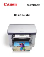
EXPLODED VIEW & PARTS LIST

Service Manual

8.8  Frame Assembly

1

6

5

11

8

9

10

15

16

18

19

20

21

22

23

24

25

27

28

29

30

31

27-1

27-2

27-3

27-4

27-5

27-7

27-6

27-4

39

54

43

44

6

45

46

47

26

51

47-1

47-2

47-3

47-4

47-5

45-1

45-2

45-3

40

41

42

32

34

T

ransfer Roller

56

35

36

48

0

2

4

3

12

13

14

16

25

33

50

6

5

53

52

7

37

17

38

37

38

49

55

Summary of Contents for Lazett Combo SCX-4216F

Page 1: ...Manual DIGITAL LASER MFP CONTENTS 1 Precautions 2 Reference Information 3 Specifications 4 Summary of product 5 Disassembly and Reassembly 6 Alignment and Adjustments 7 Troubleshooting 8 Exploded View...

Page 2: ...ung Electronics Co Ltd March 2003 Printed in Korea VERSION NO 1 00 CODE JC 0095A This service manual is also provided on the web the ITSELF system f Samsung Electronics Co Ltd http itself sec samsung...

Page 3: ...Copyright c 2003 03...

Page 4: ...ere is never any human access to laser radiation above a Class I level during nor mal operation user maintenance or prescribed service condition Warning Never operate or service the printer with the p...

Page 5: ...serted completely If not a fire will be caused due to poor contact When taking off the power plug grip the plug and remove it 7 Management of power cord Do not bend twist bind or place other materials...

Page 6: ...do not install machine near open windows damage may be caused by these conditions 5 Do not place candles burning cigarettes etc on the machine Do not install it near to a heater A fire may occur 1 2 4...

Page 7: ...am to prevent electrostatic charge buildup in the vicinity of the assembly 3 Use only a grounded tip soldering iron to solder or desolder ESDs 4 Use only an anti static solder removal device Some sold...

Page 8: ...oubleshooting described in this service manual DVM Digital Volt Meter Standard Indicates more than 3 digits 1 Tweezers Standard For general home use small type 4 Software Driver installation CD ROM 7...

Page 9: ...ed Parallel Port F W firmware GDI graphics device interface GND ground HBP Host Based Printing HDD Hard Disk Drive HV high voltage HVPS High Voltage Power Supply I F interface I O Input and Output IC...

Page 10: ...e Pattern for the Test The sample pattern shown in below is the standard pattern used in a factory The contents of the life span and the printing speed are measured with the pattern shown in below The...

Page 11: ...2 4 REFERENCE INFORMATION Samsung Electronics Service Manual 2 3 2 A4 2 Pattern...

Page 12: ...2 5 Samsung Electronics REFERENCE INFORMATION Service Manual 2 3 3 A4 IDC 5 Patten...

Page 13: ...2 6 REFERENCE INFORMATION Samsung Electronics Service Manual...

Page 14: ...lbs With Toner Cartridge LCD 16 2 Char I O Interface USB1 1 IEEE1284 Power Consumption Printing 350W Sleep Mode 20W Power Switch Yes Noise Operating SCX 4016 52 dBA SCX 4216F 4116 55 dBA Standby SCX 4...

Page 15: ...Scan Speed ADF 25 sec Text Mixed Mode seconds scan SCX 4216F 4116 B W Letter 300dpi USB 72 sec Photo Mode Gray Letter 300dpi USB Platen 23 sec Resolution Optical 600 x 600 dpi Enhanced USB 4800 x 480...

Page 16: ...DF Power Save Approx 54 seconds Stand by Approx 17 seonds Copy Speed Text Mixed SDMC 16 cpm A4 17 cpm LTR Letter MDMC 7 cpm A4 17 cpm LTR Photo SDMC 16 cpm MDMC 4 cpm Resolution Scan 600 600dpi Print...

Page 17: ...Using 3 4 buttons TAD I F No Tone Pulse Selectable in Tech Mode Pause No Auto Redial Yes Last Number Redial Yes Distinctive Ring No Caller ID No External Phone Interface No Report List Print out Tx Rx...

Page 18: ...pprox 7 5sec LTR S Fine Approx 7 5sec LTR Rx fax duplex print out No Multiple page scan speed Approx 7 ppm LTR Receive Mode Fax TEL Memory Capacity 4 MB 320 pages Optional Memory No Max locations to 9...

Page 19: ...t Bottom to Middle Front FIFO Straight Through Face up Single Sheet Paper Size Max 216 x 356mm 8 5 x14 Min 76 x 127mm 3 x5 Output Stacker Paper Extension Document Fixed Input Guide Bypass Tray Adjusta...

Page 20: ...9 Consumables Items Descriptions Remarks Type Single Cartridge How to install Front door open and front loading Toner Life Initial 1 000 sheets Initial toner life could running 3 000 sheets be differe...

Page 21: ...3 8 Specifications Samsung Electronics Service Manual...

Page 22: ...ons and operating principal of the main component 4 1 Printer Components 4 1 1 Front View Document Guides Document Input Tray Document Output Tray Control Panel Paper Tray Front Cover Paper Level Indi...

Page 23: ...RY OF PRODUCT Samsung Electronics Service Manual 4 1 2 Rear View AC Power Cord Connector Parallel Connector Power Switch USB Connector Telephone Line Connector for SCX 4216F Rear Output Slot Face up R...

Page 24: ...ying Makes a copy smaller or larger than the original Selects the number of copies Displays the current status and prompts during an operation Turns on when the toner cartridge is empty Scrolls throug...

Page 25: ...ing a one or two digit speed dial or group number for automatic dialing and edit the stored numbers Allows you to print a Phonebook list Redials the last number in Standby Mode or inserts a pause into...

Page 26: ...Confirms the selection on the display Enters Menu Mode and scrolls through the menus available Sends you back to the upper menu level Stops an operation at any time In Standby Mode clears cancels the...

Page 27: ...ing unit the fusing unit and the distributing unit 4 2 4 Fixing Part Fuser The fuser consists of the Heat Lamp Heat Roller Pressure Roller Thermistor and Thermostat It adheres toner to the paper with...

Page 28: ...e sensor In hardware aspect it is consisted of CCD module Connection board ADF board 4016 does not have ADF board AFE Analog Front End and Image Processor Located in CPU and mechanically and ADF Autom...

Page 29: ...OPC drum It is the core part of LBP The OPC drum rotates as the same speed as the paper feeding speed It creates the HS YNC signal and sends it to the engine when the laser bean of the LSU reaches th...

Page 30: ...ng roller and blade Doctor blade Developing Method Non magnetic 1 element contacting method Toner Non magnetic 1 element shatter type toner The life span of toner 3 000 sheets IDC Pattern A4 standard...

Page 31: ...he circuits on the drive motor paper feed pass clutch dri ving pre transfer lamp driving current driving and fan driving The signals from the paper feed jam sensor and paper empty sensor are directly...

Page 32: ...l DMA Control 5 channel Interrupt Control 2 port USB Host 1 port USB Device ver 1 1 Interface Control Parallel Port Interface Control UART 2 Channel Synchronous Serial Interface Control Timer 4 Channe...

Page 33: ...he photo interrupter is detected when it is passing the actuator of the sensor part That process is called developer ID sensing 4 Paper Exit Sensing It detects paper state whether paper gets out from...

Page 34: ...ply Dev and supplies it to the developer part for making the best condition to display the image The HVPS part takes the 24V and outputs the high voltage for THV MHV BIAS and the outputted high voltag...

Page 35: ...r to an OPC drum to recover toners Output Voltage 300V 150V Error Toner contamination occurs at the backside of a printed paper 4 Developing Voltage DEV Function It is a voltage to develop a toner wit...

Page 36: ...98V 264V AC 90V 135V Rated frequency 50 60 Hz Frequency fluctuating range 47 63 Hz Inputting voltage Under 4 0Arms 2 0Arms The state when lamp is off or rated voltage is inputted outputted 2 Rated Pow...

Page 37: ...controls the switch with the Triac a semicon ductor switch The On Off control is operated when the gate of the Triac is turned on off by Photo triac insulting part In the other words the AC control p...

Page 38: ...certain time The feed sensor cannot be Off After the leading edge of the paper passes the feed sensor the paper cannot reach the exit sensor after certain time The exit sensor cannot be On The paper e...

Page 39: ...D and drives the polygon motor When the receiving light part detects the beam Hsync occurs When the polygon motor speed becomes a normal LReady occurs If two conditions are satisfied the sta tus bit o...

Page 40: ...modem Also there are a ring detect circuit to detect a ring signal from a switchboard and a surge absorber to protect it from a thunderbolt located on a line input unit Ring Detect Circuit PC814 Rela...

Page 41: ...achine note the cable routing that will be affected Whenever servicing the machine you must perform as follows 1 Check to verify that documents are not stored in memory 2 Be sure to remove the toner c...

Page 42: ...Manual 5 2 Rear Cover 1 Remove the four screws securing the Rear Cover 2 Remove the Rear Cover from the Frame Ass y and Scanner Ass y 3 Unlatch the Cover Face Up securing the Rear cover as shown belo...

Page 43: ...anual 5 3 Side Cover LH RH 1 Before you remove the Side Cover LH RH you should remove Rear Cover see page 5 2 2 Unplug the Speaker Harness as shown below 3 Lift the LH and RH Side Cover out in the dir...

Page 44: ...assembly Samsung Electronics Service Manual 5 4 Front Cover 1 Take out the Cassette 2 OPen the Front Cover 3 Unlatch the Front Cover securing the Frame Ass y Then remove the Front Cover as shown below...

Page 45: ...ld remove Rear Cover see page 5 2 Side Cover LH RH see page 5 3 2 Remove the two screws securing the Scanner Ass y as shown below 3 Unplug the 6 connectors from the Connector PBA as shown below 4 Pull...

Page 46: ...three screws securing the Scan Ass y 7 Lift the OPE Unit out Then unplug the two connec tors from the OPE Unit and remove it 8 Remove the four screws securing the Scan Upper 9 Unlatch the Scan Upper s...

Page 47: ...CCD Cable as shown below 11 Push the Belt Holder and take out the Belt as shown below 12 Pull up the CCD Shaft and take out the Scanner Module 13 Remove the Reduction Gear and Idle Gear as shown below...

Page 48: ...y Samsung Electronics Service Manual 14 Remove the two screws and take out the Motor Bracket 15 Unplug the one connector from the Open Sensor Ass y 16 Unlatch the Open Sensor and remove it as shown be...

Page 49: ...the ADF Ass y and remove it 3 Remove the Open Cover as shown below 4 Pull the White Bush then rotate it until it reaches the slot as shown below Then lift the Pick Up Ass y out 5 Remove the two screw...

Page 50: ...e OPE Unit you should remove Rear Cover see page 5 2 Side Cover LH RH see page 5 3 Scanner Ass y see page 5 5 2 Remove the six screws securing the OPE PBA from the OPE Cover 3 Remove the Contact Rubbe...

Page 51: ...e 5 4 Side Cover LH RH see page 5 3 Scanner Ass y see page 5 5 2 Remove the six screws securing the Top Cover and remove it 3 Unlatch the Top Cover Securing the Frame Ass y using a proper tool as show...

Page 52: ...page 5 3 Scanner see page 5 5 2 Remove the two screws securing and unplug the FPC cable From the Main PBA Then reomve the LIU PBA 2 Unplug two connector 2 Remove the ten screws securing the Engine Shi...

Page 53: ...ve the Main PBA you should remove Rear Cover see page 5 2 Side Cover LH RH see page 5 3 Scanner see page 5 5 Engine Shield Ass y see page 5 10 2 Unplug the one connector and remove the five screws sec...

Page 54: ...5 2 Side Cover LH RH see page 5 3 Scanner Ass y see page 5 5 Engine Shield Ass y see page 5 12 2 Remove the three screws securing the Inlet Bracket and remove it 2 Unplug the one connector and remove...

Page 55: ...ain PBA and SMPS as shown below Then remove the four screws securing the Fuser Ass y and remove it 3 Remove the two screws securing the Thermostat Then lift the Thermostat out 4 Remove the two screws...

Page 56: ...sembly and Reassembly Samsung Electronics Service Manual Thermister Harness Thermister 7 Unwrap the Thermister Harness as shown below 8 Remove the one screw securing the Thermister and remove it as sh...

Page 57: ...mbly and Reassembly Service Manual 5 13 Fan 1 Before you remove the Fan you should remove Rear Cover see page 5 2 Side Cover RH see page 5 3 2 Unplug the connector from the SMPS and remove the one scr...

Page 58: ...see page 5 4 Middle Cover see page 5 11 2 Unplug the two connectors 3 Remove the four screws securing the LSU and remove it LSU 5 15 Drive Ass y 1 Before you remove the Drive Ass y you should remove R...

Page 59: ...ge 5 5 Front Cover see page 5 4 Middle Cover see page 5 11 LSU see page 5 18 2 Remove the three screws securing the Transfer Earth and remove it 3 Unplug the PTL Holder connector then remove the PTL H...

Page 60: ...ss y see page 5 5 Front Cover see page 5 4 Middle Cover see page 5 11 Drive Ass y see page 5 18 2 Remove the two screws securing the Guide Paper and remove it 3 Pull up the Feed Idle Bushing and Feed...

Page 61: ...5 21 Samsung Electronics Disassembly and Reassembly Service Manual 6 Remove the Feed Gear1 Ass y 7 Pull up the Feed Roller and Feed Roller1 Feed Gear1 Ass y Feed Roller1 Feed Roller...

Page 62: ...y see page 5 5 Middle Cover see page 5 11 Engine Shield Ass y see page 5 12 Drive Ass y see page 5 18 2 Remove the three screws securing the Feed Bracket and remove it 3 Remove the Pick Up Gear Ass y...

Page 63: ...maintenance and repair DCU using method Jam removing method and so on It includes the contents of manual 6 1 Paper path Scanner Part PTL PIC K R PR CR DR SR TR FR OPC L S U Fuser Toner Cartridge 1 2...

Page 64: ...tain time passes 4 The paper passed the paper exit sensor moves out from the set Jam 2 occurs sometime after if the tail ing edge of the paper has not exited out from the set after the leading edge of...

Page 65: ...Find and remove the jammed paper If you don t see the paper open the covers Do not use a pinset or a sharp metal tool when removing a jam The covering of a metal part can be removed which can cause an...

Page 66: ...eeding through the ADF Automatic Document Feeder DOCUMENT JAM appears on the display 6 2 1 1 Input Misfeed 1 Open the ADF top cover 2 Pull the document gently to the right and out of the ADF 3 Close t...

Page 67: ...wards the right by using both hands 3 Close the document cover Then load the documents back into the ADF 6 5 Samsung Electronics ALIGNMENT ADJUSTMENTS Service Manual 6 2 1 2 Exit Misfeed 1 Open the do...

Page 68: ...ar a jam To avoid tearing the paper pull the jammed paper out gently and slowly 6 2 2 1 JAM0 In the Paper Feed Area 1 Open and close the front cover The jammed paper automatically exits the machine If...

Page 69: ...the machine If the paper does not exit continue to Step 2 2 Gently pull the paper out of the front output tray 3 If there is any resistance when you pull the paper or the paper is not seen in the fron...

Page 70: ...the Toner Cartridge Area NOTE The fuser area is hot Be careful when removing paper from the machine 1 Open the front cover and remove the toner cartridge 2 Remove the jammed paper by gently pulling i...

Page 71: ...most paper jams can be avoided If a paper jam occurs follow the steps outlined in Clearing Paper Jams Follow the procedures in Loading Paper Ensure that the adjustable guides are positioned correctly...

Page 72: ...stem Data 8 Machine Setup Language Power Save CCD Power Save USB Mode 9 Maintenance Clean Drum Clear Memory 6 3 User Mode SCX 4116 SCX 4016 The table in the bellow explains the possible setting functi...

Page 73: ...ceive Prefix Dial No Stamp RCV Name ECM Mode 6 Reports Phone Book Send Report RCV Report System Data Scheduled Jobs Tx Confirm Junk Fax List 7 Sound Volume Speaker Ringer Key Sound Alarm sound 8 Machi...

Page 74: ...o enter the Tech mode press in sequence and the LCD briefly displays TECH the machine has entered service tech mode 2 To enter the Tech mode SCX 4116 To enter the Tech mode press in sequence and the L...

Page 75: ...er the setting value the Baud rate automatically lowers up to 2400 bps to make the error rate remain below the setting value You can select the rate between 5 and 10 CLEAR ALL MEMORY The function rese...

Page 76: ...S ROM The result and the software version appear in the LCD display FLASH VER 1 00 V ENGINE VER 1 00V PATTERN TEST Using this pattern printout you can check if the printer mechanism is functioning pro...

Page 77: ...group 3 T 30 protocol during the most recent sending or receiving operation Use this list to check for send and receive errors If a communication error occurs while the machine is in TECH mode the pr...

Page 78: ...ckUp Test 1 On 2 Off 3 Fan Test 1 On 2 Off 4 Manual Clt Test 1 On 2 Off 5 PTL Test 1 On 2 Off 1 1 LSU Motor Test 1 On 2 Off 2 LSU Hsync Test 1 On 2 Off 3 LD Test 1 On 2 Off 2 1 Feed Sen Test Check Che...

Page 79: ...the consumer first operate the machine it will start a scan and page count The time the machine was first used is remembered These settings are are remembered after memory delete Clear All Memory Meth...

Page 80: ...an average usage of 50 transmitted and received documents per day Environmental conditions and actual use will may vary The cycle period given below is for reference only COMPONENT REPLACEMENT CYCLE...

Page 81: ...Charge Roller 37 7mm Black spot 3 Supply Roller 37 0mm Horizontal density band 4 Develop Roller 35 2mm Horizontal density band 5 Transfer Roller 45 3mm Black side contamination transfer fault 6 Heat R...

Page 82: ...6 20 ALIGNMENT ADJUSTMENTS Samsung Electronics Service Manual...

Page 83: ...Cartridge EXIT Sensor Feed Sensor MP Sensor Check and Cause Solution 1 Check the Solenoid by using Engine Test Mode Diagnostic Mode code 0 2 Check if the pad is loose due to bad sealing of the side pa...

Page 84: ...is deformed Check if the lever part is deformed in shape Check whether burrs occur in the assembly part of the actuator exit or not and if the actuator is smoothly operated Check if foreign matters an...

Page 85: ...enoid if necessary 2 Clean the friction pad with soft cloth dampened with IPA Isopropyl Alcohol 3 Use the smooth paper 7 1 6 Paper rolled in the fuser Description If contaminated at intervals of 57mm...

Page 86: ...rning the OPC against the ongoing direction Clean fingerprints on the OPC softly with soft cloth dampened with IPA Isopropyl Alcohol or tis sue 7 1 8 Defective ADF Description ADF Automatic document F...

Page 87: ...y 1 Try again after clearing the memory 2 After confirming that OPE HARNESS is connected to the Connection B d correctly if it is so then replace the OPE Ass y and Main Board in sequence 7 2 2 Defecti...

Page 88: ...the cassette Check and Cause Solution 1 Bending or deformation of the actuator of the paper sen sor 2 The function of the Main PBA is defective Perform Engine Test Mode Perform Engine Test Mode diagno...

Page 89: ...tch department in the Main PBA 1 Replace the hook lever if defective 2 Check the insertion of the Door Open S W Connect 3 Replace the Main PBA or Door Open S W 7 2 7 No lamp on when the Door is open D...

Page 90: ...e 0 and Check the Motor operation 1 Check the Motor harness replace it if defective 2 Replace the SMPS if necessary 7 2 9 No Power Description When system power is turned on all lamps on the operator...

Page 91: ...tting Curved Description When printing vertical line gets curved Check and Cause Solution 1 If the supply of 24v is unstable in the Main Control board linking with LSU check drive by Engine Test Mode...

Page 92: ...Printer Digital Printer Check and Cause Solution 1 Foreign matter stuck onto the window of internal lenses of LSU mirror 2 Foreign matter or toner particles between the developer roller and blade In c...

Page 93: ...inter Digital Printer Digital Printer Digital Printer Digital Printer Check and Cause Solution 1 If dark or blurry black spots occur periodi cally the rollers in the Developer may be contaminated with...

Page 94: ...try to print out 3 No 2 Wait 30 minutes after printer is pow ered on before you start printing 4 No3 Clean up the contaminated area by the toner 5 Replace the HVPS if the problems are not solved by t...

Page 95: ...ade 1 Replace both the left and right Spring Holder 2 Problem with the toner cartridge replace the toner cartridge and try to print out 7 3 8 Background Description Light dark background appears in wh...

Page 96: ...the contaminated terminals 2 Problem in the toner cartridge replace the toner cartridge and try to print out 3 Replace the engine board if not solved by the above directions 1 2 4 If not solved by th...

Page 97: ...nter DigitalPrinter DigitalPrinter DigitalPrinter DigitalPrinter DigitalPrinter 47 mm Check and Cause Solution The temperature of the fuser is maintained high 1 Disassemble the fuser and remove the co...

Page 98: ...ormed 7 3 15 Blank Page Print out 1 Description Blank page is printed Digital Printer Digital Printer Digital Printer Digital Printer Digital Printer Check and Cause Solution Bad ground contacts in OP...

Page 99: ...y may be defective Try to replace the OPE Ass y 3 Check the Speaker connection and try to replace it 4 Lastly try to replace the Main B d 7 4 2 Defective MF DIAL Description The MF DIAL is not functi...

Page 100: ...place the LIU B d 2 If the MODEM testing is abnormal try to replace the Main B d 7 4 4 Defective FAX FORWARD Description RECEIVE is functioning but FORWARD is not functioning or the received data are...

Page 101: ...hen pressing on hook dial 2 Ask to the forwarding side check the image quality of another machine receiving a FAX additionally sent to 1 If it makes NOISE rearrange the telephone line Refer to Defecti...

Page 102: ...ot working Check and Cause Solution Check the FAX status of the forwarding side After checking the data of the forwarding side correct the FAX of the forwarding side Check and Cause Solution 1 Check i...

Page 103: ...3 Check white black reference voltage in Main PBA 1 Room light ca transit a thin original 2 Remake shading profile in the tech mode 3 Replace U60 if it is defective U60 154 0 5V U60 155 3 3V 7 5 2 Bl...

Page 104: ...age is light or bad Check and Cause Solution 1 Check shading profile 2 Check the gap between original and scanner glass 3 Check printing quality 1 Remake shading profile in the tech mode 2 The gap abo...

Page 105: ...nting test related to driver setup if it is not so rein stall it Refer to User s Manual 3 If copy function works replace the Main PBA If copy function doesn t work replace the CCD Ass y and try again...

Page 106: ...r the end of its life white streaks or light print occurs The LCD displays the warning mes sage Toner Low You can temporarily reestablish the print quality by redistributing the remaining toner in the...

Page 107: ...n the paper periodically 1 Check the cycle of the falling of the toner 2 Check the appearance of both ends of the developer OPC drum 2 The center of the printed mat ter is contaminated with toner 1 Ch...

Page 108: ...and rough printouts 1 Check whether foreign sub stance or toner are stuck to the terminal contact point of the developer 2 Check whether the state of the terminal assembly is normal 1 In case of 1 abo...

Page 109: ...heck the charged roller terminal 3 The printed image is dark and ghost occurs 1 Check foreign substance attached to the terminal point of contact of the developer and the state of assembly Especially...

Page 110: ...page 5 5 8 3 ADF Assembly Exploded view page 5 6 8 4 OPE Assembly Exploded view SCX 4216F page 5 10 8 5 OPE Assembly Exploded view SCX 4116 4016 page 5 12 8 6 Scanner Assembly Exploded view page 5 14...

Page 111: ...Samsung Electronics Service Manual 8 1 Main Assembly 13 2 15 21 3 16 4 5 7 19 23 8 18 27 10 10 1 10 2 10 3 1 2 10 4 10 5 10 6 11 20 12 12 1 12 2 12 3 14 24 25 25 2 25 2 25 1 14 1 14 2 17 2 17 1 17 3 1...

Page 112: ...CBF HARNESS LSU JC39 00242A 1 O 7 SMPS SMPS V1 HVPS JC44 00044A 1 O 110V 8 PBA MAIN MAIN JC92 01431A 1 O SCX 4216F PBA MAIN COPIER JC92 01463A 1 O SCX 4116 4016 9 MEA UNIT COVER MIDDLE JC97 01723A 1 O...

Page 113: ...1 O SCX 4216F Only 19 PBA SUB LIU_USA_EXT JC92 01481C 1 O SCX 4216F Only 20 ELA TONER UNIT 1 X 21 PLATE P CHANNEL JC61 00606A 1 O 22 PBA SUB CONN JC81 01718A 1 O 23 CBF HARNESS ENGINE JC39 00240B 1 O...

Page 114: ...t available No Description SEC Code Q ty SA Remark 0 ELA UNIT RX DRIVE JC96 02733A 1 O 1 BRACKET P GEAR 1400 1 X 2 GEAR RDCN 53 26 JC66 00388A 1 O 3 GEAR RDCN 113 33 JC66 00391A 1 O 4 GEAR RDCN 57 18...

Page 115: ...6 1 6 2 6 3 1 2 1 3 1 1 1 3 1 1 3 4 1 3 2 1 3 3 2 2 1 2 2 2 16 2 3 2 11 2 6 2 7 2 9 2 13 2 12 2 17 2 18 2 5 2 8 2 15 2 15 2 4 2 10 2 19 2 11 2 19 2 11 2 14 5 2 5 2 3 3 1 3 13 3 20 3 13 3 16 3 16 3 18...

Page 116: ...8 7 Samsung Electronics EXPLODED VIEW PARTS LIST Service Manual 4 4 1 4 3 1 4 3 4 3 2 4 3 4 4 3 3 4 3 5 4 8 4 9 4 4 4 5 4 4 4 6 4 2 S 4 7 4 7 S...

Page 117: ...O 2 6 PMO ACTUATOR DOC SENSOR JC72 01009A 1 O 2 7 PMO ACTUATOR REGI SENSOR JC72 01010A 1 O 2 8 PMO ACTUATOR SCAN SENSOR JC72 01011A 1 O 2 9 SPRING ETC TORSION DOC CC2 F JB61 00076A 3 O 2 10 IPR GROUN...

Page 118: ...87A 1 O 4 MEA UNIT COVER PLATEN JC97 01708A 1 O 4 1 COVER M PLATEN 4IN1 JC63 00146A 1 O 4 2 SHEET WHITE SPONGE 1 X 4 3 MEA TX STACKER SEC 1 X 4 3 1 PMO TX STACKER SEC JB72 01166B 1 O 4 3 2 PMO DOC GUI...

Page 119: ...8 10 EXPLODED VIEW PARTS LIST Samsung Electronics Service Manual 8 4 OPE Unit Assembly SCX 4216F 0 1 14 2 3 4 5 6 7 8 9 10 11 12 13 15...

Page 120: ...O 2 KEY M RESOLUTION JC64 00059A 1 O 3 KEY M COPY JC64 00054A 1 O 4 KEY M SCROLL JC64 00056A 1 O 5 KEY M STOP JC64 00055A 1 O 6 KEY M START JC64 00057A 1 O 7 KEY M TEL JC64 00053A 1 O 8 KEY M FAX JC64...

Page 121: ...8 12 EXPLODED VIEW PARTS LIST Samsung Electronics Service Manual 8 5 OPE Unit Assembly SCX 4116 4016 0 1 2 4 5 6 3 7 9 12 11 8 10...

Page 122: ...6 1 COVER M OPE 3IN1 JC63 00135A 1 O 2 KEY M RESOLUTION 3IN1 JC64 00051A 1 O 3 KEY M COPY 3IN1 JC64 00050A 1 O 4 KEY M SCROLL JC64 00056A 1 O 5 KEY M STOP JC64 00055A 1 O 6 KEY M START 3IN1 JC64 00057...

Page 123: ...LIST Samsung Electronics Service Manual 8 6 Scanner Assembly 0 1 1 1 1 2 1 3 1 3 1 1 3 2 1 3 3 1 3 4 2 2 1 2 2 2 3 2 5 2 6 2 7 2 14 2 8 2 9 2 11 2 10 2 16 2 12 2 13 2 4 2 15 1 2 15 4 2 15 3 2 15 2 2...

Page 124: ...63 00150A 1 O 2 2 ELA HOU CCD MODULE JC96 02821A 1 O 2 3 CBF SIGNAL CCD FFC JC39 00269A 1 O 2 4 ELA UNIT CORE 3301 001413 2 O 2 5 ICT SHAFT CCD JB70 00145A 1 O 2 6 PMO HOLDER BELT JB72 00764A 1 O 2 7...

Page 125: ...Q ty SA Remark 0 MEA UNIT COVER MIDDLE JC97 01723A 1 O 1 COVER M MIDDLE 1 X 2 PMO STACKER_RX SEC 1 X 3 RING CS 2 X 4 GEAR IDLE 23 1 X 5 PMO GEAR_EXIT_DRV16 1 X 6 GEAR EXIT F DOWN 1 X 7 MEC BEARING EXI...

Page 126: ...mbly 1 6 5 11 8 9 10 15 16 18 19 20 21 22 23 24 25 27 28 29 30 31 27 1 27 2 27 3 27 4 27 5 27 7 27 6 27 4 39 54 43 44 6 45 46 47 26 51 47 1 47 2 47 3 47 4 47 5 45 1 45 2 45 3 40 41 42 32 34 Transfer R...

Page 127: ...MO ACTUATOR CVR OPEN JC72 00974A 1 O 15 PMO PLATE GUIDE DEVE_R JC72 00985A 1 O 16 SPRING ETC GUIDE DEVE 2 X 17 IPR P GROUND_GUIDE PAPER JC70 00458A 1 O 18 PMO PLATE GUIDE DEVE_L JC72 00984A 1 O 19 PMO...

Page 128: ...JC33 00009A 1 O 44 SOLENOID HB MANUAL JC33 00010A 1 O 45 AS GEAR PICK_UP JC81 01692A 1 O 45 1 PMO GEAR PICK_UP B JC72 00980A 1 O 45 2 PMO GEAR PICK_UP A JC72 00979A 1 O 45 3 SPRING CS 1 X 46 BRACKET...

Page 129: ...8 20 EXPLODED VIEW PARTS LIST Samsung Electronics Service Manual 8 9 Fuser Assembly 0 1 2 35 3 4 5 32 32 6 33 7 8 9 10 12 13 14 15 16 17 18 19 20 21 31 25 26 27 30 28 34 29 22 23 24 11...

Page 130: ...IPR ELECTRODE_LAMP 1 X 12 ELECTRODE WIRE_L 1 X 13 THERMISTOR NTC 1404 001298 1 O 14 ELECTRODE WIRE_R 1 X 15 CBF HARNESS FUSER 110V JC39 00239A 1 O 110V WHITE 16 GEAR FUSER Z37 JC66 00564A 1 O 17 BUSH...

Page 131: ...8 22 EXPLODED VIEW PARTS LIST Samsung Electronics Service Manual 8 9 Cassette Assembly 0 1 2 3 4 5 5 18 6 7 8 9 10 11 15 16 18 12 13 14 17 18...

Page 132: ..._UP 1 X 5 SPRING CS 2 X Spring Knock_up 6 HOLDER M PAD 1 X 7 SPRING ETC EXIT ROLL FD 1 X 8 ROLLER M IDLE FEED 2 X 9 SPRING ES 2 X Spring Feed 10 PMO PLATE_LOCKER 1 X 11 SPRING ETC LOCKER PLATE 1 X 12...

Page 133: ...8 24 EXPLODED VIEW PARTS LIST Samsung Electronics Service Manual...

Page 134: ...W 24V 5V 12V 24V INLET POWER S W 2 6 P EXI T SEN SOR MP E MP SEN SO R FEED SENSO R P_ EMP SENSOR OPC GND FUSER FAN LSU MAIN MOT MAIN SOL MP SOL PTL AC PWR 2 P 2P 2P 2P 2P 3P 4P 11P EXT PHONE LINE 1 4...

Page 135: ...1 T hermistor1 2 T hermistor2 MP CLUTC H 1 2 4VS 2 Co ntrol PTL 1 3 3V 2 Co ntrol MAIN CLUTC H 1 Co ntrol 2 NC 3 2 4VS FLATE N COV ER SE NS OR 1 5V 2 Co ntrol 3 G ND5 1 3 5 7 24 GND24 2 VOUT_B 4 VOUT_...

Reviews: