


Samsung Electronics
1-4
1-4 Special Precautions and Warning Labels for Laser Products (Continued)
1-4-1 Warnings
1. When servicing, do not approach the LASER
exit with the eye too closely. In case it is
necessary to confirm LASER beam emission,
be sure to observe from a distance of more
than 30 cm from the surface of the objective
lens on the optical pick-up block.
2. Do not attempt to handle the objective lens
when the DISC is not on the tray.
1-4-2 Laser Diode Specifications
Material: GaAs+ GaAlAs
Wavelength: 760-800 nm
Emission Duration: Continuous
Laser Output: 0.2 mw (measured at a
1.6 mm distance from the objective lens
surface on the optical pick-up block.)
1-4-3 Handling the Optical Pick-up
1. Static electricity from clothing or the body
may cause electrostatic breakdown of the
laser diode in the Optical Pickup. Follow
this procedure:
2. Place a conductive sheet on the work bench
(i.e., the black sheet used for wrapping
repair parts.) Note: The surface of the work
bench should be covered by a copper
ground plane, which is grounded.
3. The repair technician must wear a wrist
strap which is grounded to the copper sheet.
4. To remove the Optical Pickup block:
Place the set on the conductive sheet, and
momentarily touch the conductive sheet
with both hands. (While working, do not
allow any electrostatic sources--such as
clothes--to touch the unit.)
5. Ground the "Short Terminal" (located on the
PCB, inside the Pickup Assembly) before
replacing the Pickup. This terminal should
be shorted whenever the Pickup Assembly
is lifted or moved.
6. After replacing the Pickup, reopen the Short
Terminal. See diagrams below:
Precautions
THE UNIT
(1) WRIST-STRAP
FOR GROUNDING
1M
1M
CONDUCTIVE SHEET
short
terminal
short terminal
short
terminal
short
terminal
SOH91VI(LDP)
SOH91CI(CAR,walkman)
SOH94T4N
(CMS-V10,CMS-V30)
SOH-A1
(CMS-V10,CMS-V30)
1-5 Special Precautions for HDD
* HDD Data Maintenance Step
1. Since the data on the HDD is weak to mechanical shock, place the HDD in a safe
location that is free from mechanical shock once it is removed from the main unit.
2. In order to safe keep the data on the HDD, back up the data before the repair or
make sure not to place the HDD near any electrical appliance that generates a strong
magnetic field.
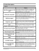
Summary of Contents for HT-X250
Page 2: ... Samsung Electronics Co Ltd JAN 2007 Printed in Korea Code no AH68 000000 ELECTRONICS ...
Page 20: ...5 4 Samsung Electronics D Separate MAIN SET ...
Page 22: ...6 1 Samsung Electronics 6 TroubleShooting 1 Main ...
Page 23: ...Samsung Electronics 6 2 2 Output ...
Page 24: ...6 3 Samsung Electronics 3 1 In case of Power Protection ...
Page 25: ...Samsung Electronics 6 4 3 2 SMPS Ass y Power check ...
Page 26: ...6 5 Samsung Electronics 3 3 AMP Pre Inspection relating to Power Protection ...
Page 27: ...Samsung Electronics 6 6 4 FAN Error Check ...
Page 28: ...6 7 Samsung Electronics 5 FAN CHECK Error ...
Page 29: ...Samsung Electronics 6 8 6 1 Communication Failure ...
Page 30: ...6 9 Samsung Electronics 6 2 Voltage Failure ...
Page 31: ...Samsung Electronics 6 10 ...
Page 32: ...6 11 Samsung Electronics 6 3 Communication Failure ...
Page 33: ...Samsung Electronics 6 12 7 Checking out AMP PCB ...
Page 34: ...6 13 Samsung Electronics 8 AMP PCB Short Check flow ...
Page 47: ...9 1 Samsung Electronics 9 Block Diagram 1 Block ...
Page 48: ...Samsung Electronics 10 1 10 Wiring Diagram 1 Wire Sheet ...
Page 49: ...10 2 Samsung Electronics 2 GND ...
Page 50: ...Samsung Electronics 10 3 3 VDD ...
Page 51: ...10 4 Samsung Electronics 4 SMPS ...
Page 52: ...11 1 Samsung Electronics 11 PCB Diagram 1 MAIN PCB ...
Page 53: ...Samsung Electronics 11 2 2 MAIN PCB Description ...
Page 54: ...11 3 Samsung Electronics 2 MAIN PCB Description ...
Page 55: ...Samsung Electronics 11 4 3 SMPS PCB ...
Page 64: ...Samsung Electronics 12 9 This Document can not be used without Samsung s authorization 2 KEY ...
Page 66: ...13 1 Samsung Electronics 13 Circuit Board Description 1 PCB Assy Layout 1 HT X250 X200 ...
Page 67: ...Samsung Electronics 13 2 2 Functional Description SMPS Main Front ...
Page 68: ...13 3 Samsung Electronics 3 Functional Description Amp HDMI Video ...
Page 69: ...Samsung Electronics 13 4 4 1 MAIN PCB Block 4 2 MAIN PCB Connectors ...
Page 70: ...13 5 Samsung Electronics 5 MAIN PCB HDMI VIDEO OUT ...
Page 71: ...Samsung Electronics 13 6 6 1 SUB PCB Block 6 2 SUB PCB Connectors ...
Page 72: ...13 7 Samsung Electronics 7 AMP PCB Block ...


