background image

17

16

1. Connect the FM antenna supplied to the FM

75

COAXIAL terminal as a temporary measure.

2. Slowly move the antenna wire around until you

find a location where reception is good, then
fasten it to a wall or other rigid surface.

1. Connect the AM loop antenna supplied to the AM    

and terminals.

2. If reception is poor, connect an outdoor single

vinyl-covered wire to the AM terminal. 
(Keep the AM loop antenna connected).

The cooling fan dissipates the heat generated inside the unit so that the unit can
be operated normally. The cooling fan is activated automatically to supply cool air
to the unit.

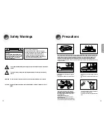
Please observe the following cautions for your safety.

Make sure the unit is well-ventilated. If the unit has poor ventilation, the temperature inside  may
rise and cause damage to it.

Do not obstruct the cooling fan or ventilation holes. (If the cooling fan or ventilation holes are
covered with a newspaper or cloth, heat may build up inside the unit and fire may result.)

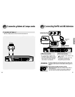
Connecting the FM and AM Antennas

FM antenna connection

If AM reception is poor, connect an
outdoor AM antenna(not supplied).

FM Antenna (supplied)

AM Loop Antenna
(supplied)

Snap the tabs on the loop into the
slots of the base to assemble the
AM loop antenna.

COOLING FAN

AM antenna connection

CONNECTIONS

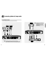
Connecting External Components 

CD Player

Before moving or installing the product, be sure to turn off the power and disconnect the power cord.

Connecting Audio Component

Summary of Contents for HT-AS610

Page 1: ...on Manual Digital Surround AV Receiver System HT AS610 AH68 01853R SAMSUNG ELECTRONICS AMERICA INC SERVICE DIVISION 400 Valley Road Suite 201 Mount Arlington NJ 07856 1 800 SAMSUNG 1 800 726 7864 www samsung com ...

Page 2: ...rsuntiltheunithasreachedroomtemperaturebeforeusing During thunderstorms disconnect AC main plug from the wall outlet Voltage peaks due to lightning could damage the unit Do not expose the unit to direct sunlight or other heat sources This could lead to overheating and malfunction of the unit The battery used with this product contain chemicals that are harmful to the environment Do not dispose of ...

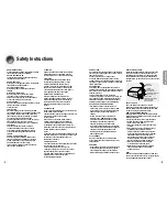
Page 3: ...WER LINES An outside antenna system should not be located in the vicinity of overhead power lines or other electric light or power circuits or where it can fall into such power lines or circuits When installing an outside antenna system extreme care should be taken to keep from touching such power lines or circuits as contact with them might be fatal POLARIZATION This video product is equipped wit...

Page 4: ...esetting Radio Stations 41 MISCELLANEOUS Convenient Functions 42 Operating your TV with the Remote Control 44 Operating your VCR DVD with the Remote Control 46 Before Calling for Service 48 Specifications 50 WARRANTY 51 PREPARATION Dolby Pro Logic II Dolby Pro Logic II is a new form of multi channel audio signal decoding technology that improves upon existing Dolby Pro Logic DTS Digital Theater Sy...

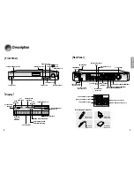
Page 5: ...NTER SPEAKER TERMINALS SURROUND SPEAKER TERMINALS Description Front Panel Display POWER button HEADPHONE Jack SELECT button TUNING button POWER STANDBY Indicator SETUP button FUNCTION button SURROUND button VOLUME CONTROL INPUT MODE button SPEAKER INDICATOR DOLBY PRO LOGIC II INDICATOR RADIO BROADCASTING RECEIVING INDICATOR RADIO STEREO INDICATOR DIGITAL INDICATOR RADIO FREQUENCY INDICATOR DTS IND...

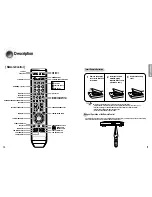
Page 6: ...t type of batteries Batteries that look similar may differ in voltage Always replace both batteries at the same time Do not expose batteries to heat or flame PREPARATION Description VOLUME CONTROL button MUTE button MENU button POWER button NUMBER 0 9 buttons INFO button SUBWOOFER button SLEEP button MO ST button TUNER button SFE MODE button STEREO button SPK LEVEL button SPK DISTANCE button EXTER...

Page 7: ...lacethesespeakersinfrontofyourlistening position facinginwards about45 towardyou Placethespeakerssothattheirtweeterswillbeat thesameheightasyourear Alignthefrontfaceofthefrontspeakerswiththe frontfaceofthecenterspeakerorplacethem slightlyinfrontofthecenterspeaker Front Speakers Itisbesttoinstallitatthesameheightasthefront speakers YoucanalsoinstallitdirectlyoverorundertheTV Center Speaker PlaceAVR...

Page 8: ...able s red plug to the red jack and white cable to the white jack CONNECTIONS Connecting External Components DVD Player or Beforemovingorinstallingtheproduct besuretoturnoffthepoweranddisconnectthepowercord Connecting Video Component Video Projector Disconnectthepowerplugfromtheoutletifyouwillnotusethisunitforalongperiodoftime EventhoughtheDigitalAudioinputsarelabelledDVDandCD youcanconnectyourDVD...

Page 9: ...upplycoolair totheunit Pleaseobservethefollowingcautionsforyoursafety Makesuretheunitiswell ventilated Iftheunithaspoorventilation thetemperatureinside may riseandcausedamagetoit Donotobstructthecoolingfanorventilationholes Ifthecoolingfanorventilationholesare coveredwithanewspaperorcloth heatmaybuildupinsidetheunitandfiremayresult Connecting the FM and AM Antennas FM antenna connection IfAMrecept...

Page 10: ...R button You can directly select CD VCR SAT DVD or TUNER OPERATION FunctionsofDedicatedRemoteControl Connect the power plug to the outlet 1 Press the POWER button of the main unit ThisunitwillbeturnedonorsettoStandbymode 2 MAIN UNIT REMOTE CONTROL You can operate your AMP this AV receiver TV DVD and VCR with this remote control See pages 44 47 for more details Press the POWER button of the remote ...

Page 11: ...CD OPTICAL or COAXIAL will be selected based on the CD setup you made on page 26 Press the INPUT MODE ANALOG button CDANALOGwillbeselected CDsetupisnotrequiredbeforeselectingtheCDAnalogmode For DVD Function Followsteps1 4inDVDsetuponpage26beforeselectingtheDVDInputMode Press the INPUT MODE button DVD OPTICAL or COAXIAL and DVD ANALOG will be selected repetitively For CD Function Followsteps1 4inCD...

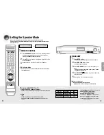
Page 12: ... Beforemovingorinstallingtheproduct besuretoturnoffthepoweranddisconnectthepowercord Frequencyresponsefromthespeakerwillbeadjustedaccordingtoyourspeakerconfigurationandwhethercertain speakersareusedornot Press SPK SELECT button to select the speaker you want Eachtimeyoupressthisbutton F SPK C SPK S SPK SW SPK CROVR SPK MODE OFF will be selected in turn Press button to set the mode Large Small etc ...

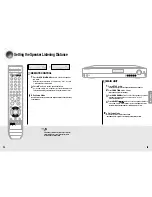
Page 13: ...ton SETUPMODEOFF appearsonthedisplayandSetupModeisexited MAIN UNIT 1 2 4 3 OPERATION Setting the Speaker Listening Distance Press the SPK DISTANCE button to select the speaker you want Each time you press this button F L CEN F R S R S L S W DIST OFF will be selected in turn Press button to set the speaker distance For F L CEN F R S W S R S L Speaker you can set the distance from the speaker to lis...

Page 14: ...e digital input Eachtimeyoupressthisbutton OPTICAL COAXIALwillbeselectedinturn 1 2 3 4 To Exit Setup Mode Waitforabout5secondsorpress SETUP button SETUPMODEOFF appearsonthedisplayandtheunitexitsSetupMode Setting DRC Dynamic Range Compression YoucanusethisfunctiontoenjoyDolbyDigitalsoundwhenwatchingmoviesatlowvolumeatnight Press SETUP button SETUPMODE appearsonthedisplayandentersintoSetupMode Press...

Page 15: ... speaker outputlevelfrom 10to 10dBby1step MAIN UNIT 1 2 3 To Stop Test Tone Press SETUP button 1 time SETUPMODEOFF appearsonthedisplayandtesttonestops F L Front Left 10 10dB CEN Center 10 10dB F R Front Right 10 10dB S R Surround Right 10 10dB S L Surround Left 10 10dB S W Subwoofer 10 10dB Test Tone Output Press SETUP button SETUPMODE appearsonthedisplayandtheunitentersintoSetupMode Press FUNCTIO...

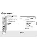
Page 16: ...urn Press SELECT button to set the speaker level you want Youcanadjustitfrom 10to 10dBby1step Thesoundgetssmallerat 10dBandlouderat 10dB Defaultsettingvalueis00dB Setting Speaker Level MAIN UNIT 1 2 4 3 OPERATION Setting Speaker Level Youcansetthebalanceandlevelofspeakers Press SPK LEVEL button to select the speaker you want Eachtimeyoupressthisbutton F L CEN F R S R S L S W SPKLVLOFFwillbeselecte...

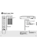
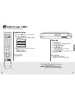
Page 17: ...n Eachtimeyoupress SELECT button CINEMA MATRIX GAME PROLOGIC MUSICwillbeselectedinturn Eachtimeyoupress SELECT button MUSIC PROLOGIC GAME MATRIX CINEMAwillbeselectedinturn Dolby Pro Logic ll Mode To Exit Setup Mode Waitforabout5seconds MAIN UNIT 1 2 OPERATION Dolby Pro Logic ll Mode Thismodeprovides5 1channelsoundfrom2channelsources Press MODE button Eachtimeyoupressthisbutton CINEMA MATRIX GAME P...

Page 18: ...Mode Press FUNCTION button 10 times DPLll MODE appearsonthedisplay Press SURROUND button Eachtimeyoupressthisbutton C WIDTH DIMENSION PANORAMA willbeselectedinturn Press SELECT button to select Dolby Pro Logic ll effect you want Dolby Pro Logic ll Effect MAIN UNIT 1 2 4 3 OPERATION Dolby Pro Logic ll Effect ThisfunctionworksonlyinDolby PRO LOGIC II MUSIC Mode Press MODE button to select MUSIC Mode...

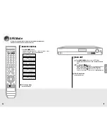
Page 19: ...ct button CHURCH STADIUM DOME CLUB ARENA THEATER HALL willbeselectedinturn To Exit Setup Mode Waitforabout5seconds MAIN UNIT 1 2 OPERATION SFE Mode TheSFE SoundFieldEffect functionuses7differentDSPsoundfieldeffectstodigitallysimulate actualmusicenvironmentssuchasconcerthallsormovietheaters Press SFE MODE button Eachtimeyoupressthisbutton HALL THEATER ARENA CLUB DOME STADIUM CHURCH willbeselectedin...

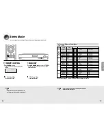
Page 20: ...SW Dolby D 5 1ch Dolby Digital 5 1 O O O O DIGITAL L C R SL SR SW DolbyD 2ch ProLogicII O O O O DIGITAL L C R SL SR SW DolbyD 2chSurr ProLogicII O O O O DIGITAL L C R SL SR SW L PCM Audio ProLogicII O O O O L PCM L C R SL SR SW Analog ProLogicII O O O O ANALOG L C R SL SR SW DTS ES DTS 5 1 O O O O DTS L C R SL SR SW DTS 96 24 DTS 5 1 O O O O DTS L C R SL SR SW DTS 5 1 DTS 5 1 O O O O DTS L C R SL ...

Page 21: ...cted Select frequency Automatic Tuning 1 1 Press TUNING MODE buttontoselectPRESET 2 Press TUNING CH buttontoselectthepreset frequency Automatic Tuning 2 1 Press TUNING MODE buttontoselectMANUAL 2 Pressandhold TUNING CH buttonto automaticallytuneinfrequency Manual Tuning 1 Press TUNING MODE buttontoselectMANUAL 2 Press TUNING CH buttonbrieflytoincreaseor decreasethefrequencystepbystep Press FUNCTIO...

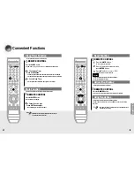
Page 22: ...SETfunctionwilleraseallstoredsettings Donotusethisunlessnecessary 1 2 3 Convenient Functions Press the SLEEP button SLEEP OFF 15 30 45 60 90 120MINwillbeselectedinturn Youcansetthetimethatthisunitwillshutitselfoff To Check Sleep Timer Press SLEEP button Theremainingtimebeforethisunitwillshutitselfoffisshownonthedisplay Pressingthebuttonagainchangesthesleeptimefromwhatyousetpreviously To Cancel Sle...

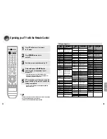
Page 23: ...TIC 003 019 SAMPO 040 SAMSUNG 000 015 016 017 040 043 046 047 048 049 054 059 060 098 SANYO 019 061 065 101 102 103 104 SCOTT 003 040 060 061 SEARS 015 018 019 SHARP 015 057 064 101 105 106 115 SIGNATURE2000 M WARDS 057 058 SONY 050 051 052 053 055 101 SOUNDESIGN 003 040 SPECTRICON 001 SSS 018 SYLVANIA 018 040 048 054 059 060 062 SYMPHONIC 061 095 096 TATUNG 006 TECHWOOD 018 TEKNIKA 003 015 018 02...

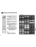
Page 24: ...ANSUI 092 SCOTT 006 051 054 057 069 070 100 101 SEARS 020 021 025 SHARP 043 105 106 SINGER 096 SIGNATURE2000 M WARDS 043 044 054 100 106 SHINTOM 096 SONY 034 035 036 037 038 039 040 041 042 082 083 084 085 086 STS 020 SYLVANIA 001 033 044 049 066 091 SYMPHONIC 044 TANDY 009 TASHIRO 050 TATUNG 047 052 092 TEAC 044 047 052 092 TECHNICS 001 033 049 091 TEKNIKA 001 025 033 TOSHIBA 006 051 TOTEVISION 0...

Page 25: ...EinSpeakerSetup IstheSurroundModeselectedtoStereo Refertopages12 13toconnectitproperly Refertopages 22 23 toselectLARGEor SMALL Refertopages33 39toselectother SurroundModes Remote controller does not work There is no sound from surround speakers The sound from each device is changed during stereo playback Can t receive radio broadcasts IsAMorFMantennaconnected properly Are the batteries drained Is...

Page 26: ...nd software products if provided are on an AS IS basis Non SAMSUNG manufacturers suppliers publishers and service providers may provide their own warranties This limited warranty covers manufacturing defects in materials and workmanship encountered in normal and except to the extent otherwise expressly provided for in this statement noncommercial use of this product and shall not apply to the foll...

Reviews: