Samsung HT-AS600 Instruction Manual Download Page 3

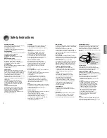
READ INSTRUCTIONS
All the safety and operating instructions should be
read before the appliance is operated.

RETAIN INSTRUCTIONS
The safety and operating instructions should be
retained for future reference.

HEED WARNINGS
All warnings on the appliance and in the operating
instructions should be adhered to.

FOLLOW INSTRUCTIONS
All operating and use instructions should be 
followed.
WATER AND MOISTURE
Do not use this video product near water-
for example, near a bathtub, wash bowl,  
kitchen sink, or laundry tub, in a wet basement, 
or near a swimming pool, and the like.

OVERLOADING
Do not overload wall outlets and extension cords as
this can result in the risk of fire 
or electric shock.

VENTILATION
Slots and openings in the cabinet are provided 
for ventilation and to ensure reliable operation of the
video product and to protect it from overheating
these openings must not be blocked or covered.
The openings should never be blocked 
by placing the video product on a bed, sofa, rug, or
other similar surface. This video product 
should never be placed near or over a radiator or
heat register.
This video product should not be placed 
in a built-in installation such as a bookcase 
or rack unless proper ventilation is provided 
or the manufacturer's instructions have been
followed.

POWER CORD PROTECTION
Power-supply cords should be routed so that
they are not likely to be walked on or pinched
by items placed upon or against them paying
particular attention to cords at plugs,
convenience receptacles, and the point where
they exit from the appliance.

CLEANING
Unplug this video product from the wall outlet
before cleaning. Do not use liquid cleaners 
or aerosol cleaners. Use a damp cloth for cleaning.

LIGHTNING
For added protection of this video product
receiver during a lightning storm, or when 
it is left unattended and unused for long 
periods of time, unplug it from the wall outlet
and disconnect the antenna or cable system. 
This will prevent damage to the video product 
due to lightning and power-line surges.

OBJECT AND LIQUID ENTRY
Never push objects of any kind into this 
product through openings as they may touch
dangerous voltage points or short-out parts
that could result in a fire or electric shock.
Never spill liquid of any kind on the video
product.

ACCESSORIES
Do not place this video product on an unstable cart,
stand, tripod, bracket, or table. 
The video product may fall, causing serious injury to
a child or adult, and serious damage 
to the appliance.
Use only with a cart, stand, tripod, bracket, 
or table recommended by the manufacturer, 
or sold with the video product. Any mounting 
of the appliance should follow the manufacturer's
instructions and should use a mounting accessory
recommended by the manufacturer.

CART
An appliance and cart combination should be moved
with care. Quick stops, excessive force, and uneven
surfaces may cause the appliance and cart
combination to overturn.

POWER SOURCES
This video product should be operated only from the
type of power source indicated 
on the marking label. If you are not sure 
of the type of supply to your home, consult your
appliance dealer or local power company. 
For video products intended to be operated from
battery power, or other sources, refer 
to the operating instructions.

POWER LINES
An outside antenna system should not be located in
the vicinity of overhead power lines or other electric
light or power circuits, 
or where it can fall into such power lines 
or circuits. When installing an outside antenna
system, extreme care should be taken to keep from
touching such power lines or circuits as contact with
them might be fatal.

POLARIZATION
This video product is equipped with a polarized 
alternating current line plug (a plug having one blade
wider than the other.) This plug will fit into the power
outlet only one way. 
This is a safety feature. If you are unable 
to insert the plug fully into the outlet, try reversing the
plug. If the plug should still fail to fit, contact your
electrician to replace your obsolete outlet. Do not
defeat the safety purpose of the polarized plug.

OUTDOOR ANTENNA GROUNDING

If an outside antenna is connected to the 

antenna terminal, be sure the antenna system 
is grounded so as to provide some protection   
against voltage surges and built-up static 
charges.

In the U.S.A section 810 of the National   

Electrical Code, ANSI/NFPA No. 70-1984, 
provides information with respect to proper  
grounding of the mast and supporting 
structure, grounding of the lead-in wire 
to an antenna discharge unit, size of grounding 
conductors, location of antenna discharge unit,  
connection to grounding electrodes, and 
requirements for the grounding electrode. 
See the figure below.

ATTACHMENTS
Do not use attachments not recommended 
by the video product manufacturer as they may
cause hazards.

SERVICING

Do not attempt to service this product yourself 

as opening or removing covers may expose 
you to dangerous voltage or other hazards.

Refer all servicing to qualified service personnel.

REPLACEMENT PARTS
When replacement parts are required, be sure the
service technician has used replacement parts
specified by the manufacturer or having the same
characteristics as the original part. Unauthorized
substitutions may result in fire, electric shock or other
hazards.

SAFETY CHECK
Upon completion of any service or repairs 
to this video product, ask the service technician to
perform safety checks to determine that the video
product is in proper operating condition.

DAMAGE REQUIRING SERVICE
Unplug this video product from the wall outlet and
refer servicing to qualified service personnel under the
following conditions.
a. When the power-supply cord or plug is damaged.
b. If liquid has been spilled, or objects have 

fallen into the video product.

c. If the video product has been exposed to rain 

or water

d. If the video product does not operate normally

by following the operating instructions. 
Adjust only those controls that are covered 
by the operating instructions as an improper 
adjustment of other controls may result 
in damage and will often require extensive 
work by a qualified technician to restore 
the video product to its normal operation.

e. If the video product has been dropped 

or the cabinet has been damaged.

f. When the video product exhibits a distinct 

change in performance - this indicates 
a need for service.

HEAT
This video unit should be situated away from heat
sources such as radiators, stoves, or other products
(including amplifiers) that produce heat.

ANTENNA
LEAD IN WIRE

ANTENNA
DISCHARGE UNIT
(NEC SECTION. 810-20)

GROUNDING CONDUCTORS
(NEC SECTION 810-21)

GROUND CLAMPS

POWER SERVICE GROUNDING
ELECTRODE SYSTEM
(NEC ART 250, PART H)

GROUND
CLAMP

ELECTRIC
SERVICE
EQUIPMENT

PREP

ARA

TION

Safety Instructions

4

3

Summary of Contents for HT-AS600

Page 1: ...truction Manual Digital Surround AV Receiver System HT AS600 SAMSUNG ELECTRONICS AMERICA INC SERVICE DIVISION 400 Valley Road Suite 201 Mount Arlington NJ 07856 1 800 SAMSUNG 1 800 726 7864 www samsung com AH68 01725R ...

Page 2: ... approximately 2 hours until the unit has reached room temperature before using During thunderstorms disconnect AC main plug from the wall outlet Voltage peaks due to lightning could damage the unit Do not expose the unit to direct sunlight or other heat sources This could lead to overheating and malfunction of the unit The battery used with this product contain chemicals that are harmful to the e...

Page 3: ...LINES An outside antenna system should not be located in the vicinity of overhead power lines or other electric light or power circuits or where it can fall into such power lines or circuits When installing an outside antenna system extreme care should be taken to keep from touching such power lines or circuits as contact with them might be fatal POLARIZATION This video product is equipped with a ...

Page 4: ...eaker Level 27 Dolby Pro Logic ll Mode 29 Dolby Pro Logic ll Effect 31 SFE Mode 33 Stereo Mode 35 RADIO OPERATION Listening to Radio 37 Presetting Radio Stations 38 MISCELLANEOUS Convenient Functions 39 Operating TV with Remote Control 41 Operating VCR DVD with Remote Control 43 Before Calling for Service 45 Specifications 47 WARRANTY 48 PREPARATION Dolby Pro Logic II Dolby Pro Logic II is a new f...

Page 5: ...SURROUND SPEAKER TERMINALS Description Front Panel Display POWER button VOLUME CONTROL REMOTE CONTROL Sensor ANALOG DIGITAL BUTTON SELECTION button TUNER button POWER STANDBY Indicator SETUP button SURROUND button HEADPHONE Jack INPUT button 7 SPEAKER INDICATOR DOLBY PRO LOGIC II INDICATOR RADIO BROADCASTING RECEIVING INDICATOR RADIO STEREO INDICATOR DIGITAL INDICATOR RADIO FREQUENCY INDICATOR DTS...

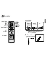
Page 6: ...atteries Place batteries in the remote control so they match the polarity to and to Use the correct type of batteries Batteries that look similar may differ in voltage Always replace both batteries at the same time Do not expose batteries to heat or flame PREPARATION Description VOLUME CONTROL button MUTE button MENU button ANALOG DIGITAL button POWER button TV VIDEO FUNCTION button SLEEP button T...

Page 7: ...m place these speakers so they face each other Place them about 60 to 90cm 2 to 3feet above your ear facing slightly downward Unlike the front and center speakers the surround speakers are used to handle mainly sound effects and sound will not come from them all the time Surround Speakers SL SR Place these speakers in front of your listening position facing inwards about 45 toward you Place the sp...

Page 8: ... the right or left Audio Input jack of the main unit Connect the audio cable s red plug to the red jack and white cable to the white jack 14 CONNECTIONS Connecting External Components DVD Player Before moving or installing the product be sure to turn off the power and disconnect the power cord Connecting Video Component 13 Video Projector Disconnect the power plug from the outlet if you do not use...

Page 9: ...wing cautions for your safety Make sure the unit is well ventilated If the unit has poor ventilation the temperature inside the unit could rise and may damage it Do not obstruct the cooling fan or ventilation holes If the cooling fan or ventilation holes are covered with a newspaper or cloth heat may build up inside the unit and fire may result Connecting the FM and AM Antennas FM antenna connecti...

Page 10: ...Press the FUNCTION button Each time you press the this button CD DVD VCR SAT FM AM will be selected in turn OPERATION Before Using the AV Receiver Turning On Off Functions of Dedicated Remote Control Connect the power plug to the outlet 1 Press the POWER button of the main unit This unit will be turned on or off 2 MAIN UNIT REMOTE CONTROL Press MODE button Each time you press this button it will s...

Page 11: ...ct 80Hz for 4 8inch 100Hz for 4inch 120Hz for 3 2inch 150Hz for 2 4inch 180Hz and 200Hz for 1 6inch 20 F SPK Front LARGE SMALL C SPK Center LARGE SMALL NONE S SPK Surround LARGE SMALL NONE SW SPK Subwoofer YES NO CROVR Crossover Frequency 60 80 100 120 150 180 200Hz SettingtheSpeaker MAIN UNIT 1 2 4 3 OPERATION Setting the Speaker Mode Before moving or installing the product be sure to turn off th...

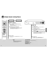
Page 12: ...ion between 0 0 4 5m in intervals of 0 3m Setting Speaker Distance To Exit Setup Mode Wait for about 5 seconds or turn the VOLUME CONTROL of the main unit SETUP MODE OFF appears on the display and exit Setup Mode MAIN UNIT 1 2 4 3 OPERATION Setting the Speaker Listening Distance Press the SPEAKER DISTANCE button to select the speaker you want Each time you press this button F L CEN F R S R S L S W...

Page 13: ...to enjoy Dolby Digital sound when watching movies at low volume at night Press SETUP button SETUP MODE appears on the display and enters into Setup Mode Press INPUT button 3 times DRC SETUP appears on the display Press SURROUND button to set DRC Each time you press this button DRC STD DRC MAX DRC MIN will be selected in turn To Exit Setup Mode Wait for about 5 seconds or turn the VOLUME CONTROL of...

Page 14: ... time TEST T OFF appears on the display and test signal stops Method 2 Turn VOLUME CONTROL SETUP MODE OFF appears on the display and test tone stops OPERATION 25 Test Tone Use test tone to check speaker connection status or level Press SETUP button SETUP MODE appears on the display and enters into Setup Mode Press INPUT button 4 times TEST T AUTO appears in the display Press SURROUND button Test s...

Page 15: ...T button to set to the speaker level you want You can adjust it from 10 to 10dB by 1 step The sound gets smaller at 10dB and louder at 10dB Default setting value is 00dB Setting Speaker Level MAIN UNIT 1 2 4 3 OPERATION Setting Speaker Level You can set the balance and level of speakers Press SPK LEVEL button to select the speaker you want Each time you press this button F L CEN F R S R S L S W SP...

Page 16: ...will be selected in turn Each time you press SELECT button PROLOGIC MATRIX CINEMA MUSIC will be selected in turn Dolby Pro Logic ll Mode To Exit Setup Mode Wait for about 5 seconds MAIN UNIT 1 2 OPERATION Dolby Pro Logic ll Mode This mode provides 5 1 channel sound from 2 channel sources Press MODE button Each time you press this button MUSIC CINEMA MATRIX PROLOGIC will be selected in turn 29 To E...

Page 17: ... ll MODE appears on the display Press SURROUND button Each time you press this button C WIDTH DIMENSION PANORAMA will be selected in turn Press SELECT button to select Dolby Pro Logic ll effect you want Dolby Pro Logic ll Effect MAIN UNIT 1 2 4 3 OPERATION Dolby Pro Logic ll Effect This function works only in Dolby PRO LOGIC II MUSIC Mode Press MODE button to select MUSIC Mode Press EFFECT button ...

Page 18: ...ss Select button CHURCH STADIUM DOME CLUB ARENA THEATER HALL will be selected in turn To Exit Setup Mode Wait for about 5 seconds MAIN UNIT 1 2 OPERATION SFE Mode Refer to the unique sound existing at specific place and you can feel live sound as if you are listening at actual site Press SFE MODE button Each time you press this button HALL THEATER ARENA CLUB DOME STADIUM CHURCH will be selected in...

Page 19: ... O O L PCM L R Analog SFE O O O O ANALOG Dolby D Surr EX Dolby Digital EX O O O O DIGITAL L C R SL SR SW Dolby D 5 1ch Dolby Digital EX O O O O DIGITAL L C R SL SR SW DTS ES DTS ES O O O O dts ES L C R SL SR SW DTS 5 1ch DTS ES O O O O dts L C R SL SR SW Dolby Surr EX Stereo O O DIGITAL L C R SL SR SW Dolby D 5 1ch Stereo O O DIGITAL L C R SL SR SW Dolby D 2ch Stereo O DIGITAL L R Dolby D 2ch Surr...

Page 20: ...button FM AM will be repetitively selected Select frequency Automatic Tuning 1 1 Press ENTER button to select PRESET 2 Press TUNING CH button to select the preset frequency Automatic Tuning 2 1 Press ENTER button to select MANUAL 2 Press and hold TUNING CH button to automatically tune in frequency Manual Tuning 1 Press ENTER button to select MANUAL 2 Press TUNING CH button briefly to increase or d...

Page 21: ... all stored settings Do not use this unless necessary Caution 1 2 3 Convenient Functions Press the SLEEP button SLEEP OFF 15 30 45 60 90 120MINwillbeselectedinturn You can set the time that this unit will shut itself off To Check Sleep Timer Press SLEEP button The remaining time before this unit will shut itself off is shown on the display Pressing the button again changes the sleep time from what...

Page 22: ...SAMSUNG 000 015 016 017 040 043 046 047 048 049 054 059 060 098 SANYO 019 061 065 101 102 103 104 SCOTT 003 040 060 061 SEARS 015 018 019 SHARP 015 057 064 101 105 106 115 SIGNATURE2000 M WARDS 057 058 SONY 050 051 052 053 055 101 SOUNDESIGN 003 040 SPECTRICON 001 SSS 018 SYLVANIA 018 040 048 054 059 060 062 SYMPHONIC 061 095 096 TATUNG 006 TECHWOOD 018 TEKNIKA 003 015 018 025 TMK 018 040 TOSHIBA ...

Page 23: ...100 101 SEARS 020 021 025 SHARP 043 105 106 SINGER 096 SIGNATURE2000 M WARDS 043 044 054 100 106 SHINTOM 096 SONY 034 035 036 037 038 039 040 041 042 082 083 084 085 086 STS 020 SYLVANIA 001 033 044 049 066 091 SYMPHONIC 044 TANDY 009 TASHIRO 050 TATUNG 047 052 092 TEAC 044 047 052 092 TECHNICS 001 033 049 091 TEKNIKA 001 025 033 TOSHIBA 006 051 TOTEVISION 025 072 TAEKWANG 087 UNITECH 072 VECTORRE...

Page 24: ...NONEin SpeakerSetup IstheSurroundModeselectedtoStereo Refer to pages 11 12 to connect it properly Refer to pages 19 20 to select LARGE or SMALL Refer to pages 20 36 to select other Surround Modes Remote controller does not work There is no sound from surround speaker The sound from each device is changed during stereo playback Can t receive broadcasting Is AM or FM antenna connected properly Are t...

Page 25: ... apply to the following including but not limited to damage which occurs in shipment delivery and installation applications and uses for which this product was not intended altered product or serial numbers cosmetic damage or exterior finish accidents abuse neglect fire water lightning or other acts of nature use of products equipment systems utilities services parts supplies accessories applicati...

Page 26: ... fi FRANCE 08 25 08 65 65 0 15 Min www samsung com fr GERMANY 01805 121213 0 12 Min www samsung de HUNGARY 06 40 985 985 www samsung com hu ITALIA 199 153 153 www samsung com it LUXEMBURG 02 261 03 710 www samsung lu NETHERLANDS 0900 20 200 88 0 10 Min www samsung com nl NORWAY 231 627 22 www samsung com no POLAND 0 801 801 881 www samsung com pl PORTUGAL 80 8 200 128 www samsung com pt SLOVAKIA 0...

Reviews: