background image

4-2. How to Check Fault Symptom

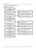
NO Power and No Video


„

Power cord on.

Yes

Check ‘Stand-By A19V_PW’ 19V appear 

at BD213 or BD210 or BD212?

No

Cause

 :  There did not supply the power from SMPS.

Measure

 :  Change 10P power cable and SMPS.

Yes

Check Function board LED light 

Standby mode:  ON

No

Cause

 :  Sub micom IC did not control the Function.

Measure

 :  Change the Main Assy or change Function

Yes

Power On

Yes

The Remote control act.

No

Cause

 : Remote control has no battery.

Measure

 :  Change the battery.

Yes

Check ‘TP_SW_POWER’ ? 

3.3V : Standby 0V : Power on 

No

Cause

 :  Sub micom IC did not control the SW_Power.

Measure

 : Change the Main Assy.

Yes

Check ‘Power of LVDS (13V)’ appear at 

TP-PANEL_VCC?

0V to 13V (TP-PANEL_VCC)

No

Cause

 :  There is proble at FET(Q202_NFRC) or Main 

IC(NT14L) did not control the SW_PVCC.

Measure

 :  Change the Main Assy.

Yes

Change the LVDS cable.

No

Change the Panel.

Yes

OK

4-2 

4. Troubleshooting

Summary of Contents for HG32ED470SK

Page 1: ...LED TV SERVICE Manual Hospitality Displays Contents 1 Precautions 2 Product specifications 3 Disassembly and Reassembly 4 Troubleshooting 5 Wiring Diagram HG32ED470SK Chassis HED58 Model HG32ED470SK ...
Page 2: ...s 2 7 2 4 Viewing the Functions 2 8 2 4 1 Hotel Plug Play 2 8 2 4 2 HD Plug Play Local Set 2 9 3 Disassembly and Reassembly 3 1 3 1 Disassembly and Reassembly 3 1 4 Troubleshooting 4 1 4 1 Previous Check 4 1 4 2 How to Check Fault Symptom 4 2 4 3 Factory Mode Adjustments 4 3 4 3 1 Detail Factory Option 4 3 4 3 2 Entering Factory Mode 4 4 4 3 3 Factory Data 4 5 4 4 White Balance 4 18 4 4 1 Calibrat...
Page 3: ...ANNEX Exploded View Part List HG32ED470SKXEN LP02 ANNEX 1 1 1 Exploded View ANNEX 1 1 1 1 Part List ANNEX 1 2 1 Electrical Parts List ANNEX 2 ...

Page 4: ...anual is a property of Samsung Electronics Co Ltd Any unauthorized use of Manual can be punished under applicable International and or domestic law 2015 Samsung Electronics Co Ltd All rights reserved Printed in Korea ...

Page 5: ...embly CAUTION Disconnect the LED TV from the power source before disassembly 1 Follow these directions carefully never use metal instruments to pry apart the cabinet 2 If there is no additional coment it is same for all inches 3 Description Picture Description Screws 1 Place a soft cloth over the table to protect the TV and then place the TV on the cloth screen side down 2 Remove the screws from t...

Page 6: ...ASSY COVER P REAR 6 Remove the Power Cables and Speaker Cables Power Cable Speaker Cable Power Cable Remove the LVDS Cable ASSY BOARD P JOG SWITCH IR Cable LVDS Cable LVDS Cable ASSY BOARD P JOG SWITCH IR 7 Remove the screws of ASSY PCB MAIN and DC VSS LED TV PD BD ASSY PCB MAIN 4EA DC VSS LED TV PD BD 5EA 6001 003016 SCREW MACHINE M3 0 L5 0 ZPC WHT 8 Remove the ASSY SPEAKER L R ...

Page 7: ...3 3 3 Disassembly and Reassemble Description Picture Description Screws 9 Completed disassembly NOTE Reassembly procedures are in the reverse order of disassembly procedures ...

Page 8: ...D470S NEW_CIS NEW_EUROP 1 SA 3 1 BN61 12065A HOLDER SIDE AV Y15 J4003 32 EO SMART 1 SNA 4 BN96 37286B ASSY BOARD P JOG SWITCH IR HD470S 32 1 SA 5 BN96 36052A ASSY SPEAKER P 6ohm 4pin 5W J4003 1 SA 6 BN63 14019M COVER REAR J4003 32 Hotel HD470S_EU ABS 1 SA 7 BN96 37255A ASSY STAND P BASE J4003 Arc Feet Matt BL 1 SA ANNEX Exploded View Part List HG32ED470SKXEN LP02 1 1 Exploded View ANNEX 1 ANNEX Ex...

Page 9: ...16 SNA 3 FB01A BN97 07120D ASSY DRM KEY NT14L_DRM KEY CI 1 SNA 4 BN46 00328B KEY CODE CERTIFI CI TV NT14 EU 1 SNA 3 BN97 08104Z ASSY SMD UH4A UH4A 1 SNA 4 0202 001830 SOLDER CREAM LFM 48W TM HP D20 38um 96 5 4 SNA 4 DS01A 0401 001056 DIODE SWITCHING MMBD4148SE 100V 200mA SO 2 SA 4 DS01A 0401 001099 DIODE SWITCHING 1N4148WS 75V 150mA SOD 3 3 SA 4 DS01A 0401 001116 DIODE SWITCHING BAV99DW 75V 215mA ...

Page 10: ...E800 HSOP 8 1 SNA 4 1203 008105 IC POSI FIXED REG S 13A1D33 E800 HSOP 8 1 SNA 4 1203 008496 IC BACKLIGHT DRIVER BD9397EFV HTSSOP B40 1 SA 4 1204 003492 IC DECODER SENK14 LFBGA 624P 21x21mm PLA 1 SA 4 1205 004447 IC SWITCH TPS2051CDBVR SOT23 5 5P 3x1 65 2 SA 4 1405 001271 VARISTOR 35V 20Vdc 5A 1 0x0 5x0 6mm TP 1 18 SA 4 2007 000029 R CHIP 0ohm 5 1 8W TP 2012 3 SC 4 2007 000039 R CHIP 0ohm 1 1 10W T...

Page 11: ... 007132 R CHIP 15Kohm 1 1 16W TP 1005 1 SA 4 2007 007134 R CHIP 39Kohm 1 1 16W TP 1005 2 SA 4 2007 007136 R CHIP 4 7Kohm 1 1 16W TP 1005 2 SNA 4 2007 007138 R CHIP 27Kohm 1 1 16W TP 1005 3 SA 4 2007 007139 R CHIP 47Kohm 1 1 16W TP 1005 1 SA 4 2007 007142 R CHIP 10Kohm 1 1 16W TP 1005 2 SNA 4 2007 007156 R CHIP 1ohm 5 1 16W TP 1005 18 SNA 4 2007 007231 R CHIP 110Kohm 1 1 10W TP 1608 2 SA 4 2007 007...

Page 12: ... 50V X7R TP 1005 3 SA 4 AD480 2203 000585 C CER CHIP 0 22nF 10 50V X7R TP 1005 1 SA 4 AD480 2203 000627 C CER CHIP 0 022nF 5 50V C0G TP 1005 2 SNA 4 AD480 2203 000714 C CER CHIP 3 3nF 10 50V X7R TP 1005 11 SA 4 AD480 2203 000812 C CER CHIP 0 033nF 5 50V C0G TP 1005 1 SA 4 AD480 2203 000854 C CER CHIP 0 039nF 5 50V C0G TP 1005 1 SA 4 AD480 2203 000940 C CER CHIP 0 47nF 10 50V X7R TP 1005 3 SA 4 AD4...

Page 13: ... 32 1 SA 4 2703 003149 INDUCTOR SMD 2 2uH 20 5050 0 055Ohm 300 3 SA 4 2703 004145 INDUCTOR SMD 2 2uH 20 6 5 x 6 9mm 0 20o 1 SNA 4 2703 004457 INDUCTOR SMD 10uH 20 8080 4 5T 0 074O 1 SNA 4 2703 004724 INDUCTOR SMD 8 2uH 20 5050 4mm 0 072Ohm 4 SA 4 2703 005289 INDUCTOR SMD 33uH 20 15x16mm 8 5mm 0 05 1 SA 4 2801 000258 CRYSTAL SMD 0 032768MHz 20ppm SMD 12 5pF 1 SA 4 2801 003773 CRYSTAL SMD 12MHz 30pp...

Page 14: ... CB A 01 SW2 W914 D11 1 SNA 1 BN92 17537A ASSY P MATERIAL HD470 1 SNA 0 2 6902 002498 BAG ROLL HDPE PE FOAM T0 5 W650 L300M T 2 SNA 0 2 6922 000013 BAND PP W18 L2300 L2900 TRP 1 SNA 0 2 BN01 00039A FOIL STRETCH HOOD LLDPE T0 08 W930 L1400 0 SNA 0 2 AS080 BN63 10787F SHEET COVER UE22ES5000 PE T4 0 W1020 L11 1 SNA 0 2 BN69 08447A PAD COMM CB SW2 T3 W800 L1000 YE 1 SNA 0 2 BN69 11850A CUSHION SET J40...

Page 15: ...Remark 4 AH365 BN61 07295A HOLDER RING 40UD5500 ABS BK0007 HB 4 SC 5 0103 004609 RESIN ABS HF 0680U K21294 BK0007 1 5mm H 16 SNA 1 BN92 17807A ASSY LABEL HD470 1 SNA 0 2 BN68 06708E LABEL RATING ALL WW PP T0 05 93 73 Dark 1 SNA ANNEX 8 ANNEX Exploded View Part List ...

Page 16: ...s adjustment and 2 compartment covers or shields isolation resistorcapacitor networks mechanical insulators etc Leakage Current Hot Check 3 DEVICE UNDER TEST READING SHOULD NOT BE ABOVE 0 5mA LEAKAGE CURRENT TESTER TEST ALL EXPOSED METAL SURFACES 2 WIRE CORD ALSO TEST WITH PLUG REVERSED USING AC ADAPTER PLUG AS REQUIRED EARTH GROUND WARNING Do not use an isolation transformer during this test Use ...

Page 17: ...ed by replacing them with components rated for higher voltage wattage etc Parts that have special safety characteristics are identified by on schematics and parts lists A substitute replacement that does not have the same safety characteristics as the recommended replacement part might create shock fire and or other hazards Product safety is under review continuously and new instructions are issue...

Page 18: ... used 2 The internal wiring is sometimes clamped to prevent contact with thermally hot components Reinstall all such elements to their original position After servicing always check that the screws components and wiring have been correctly reinstalled Make sure that 3 the area around the serviced part has not been damaged Check the insulation between the blades of the AC plug and accessible conduc...

Page 19: ...s sufficient to damage ESDs 3 Use only a grounded tip soldering iron to solder or desolder ESDs 4 Use only an anti static solder removal device Some solder removal devices not classified as anti static can generate 5 electrical charges sufficient to damage ESDs Do not remove a replacement ESD from its protective package until you are ready to install it Most replacement ESDs 6 are packaged with le...

Page 20: ...antenna far away from any high voltage cables and install it firmly Contact with the highvoltage cable or the 6 antenna falling over may cause fire or electric shock When installing the product leave enough space 0 4m between the product and the wall for ventilation purposes 7 A rise in temperature within the product may cause fire If an equipment is provided with a replaceable battery and if repl...

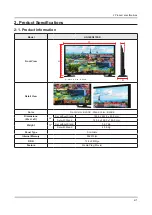
Page 21: ...igh D Depth H Detail View Color Front Color BLACK Stand Color BLACK Dimensions W x H x D 32 Set without Stand 745 4 x 442 2 x 69 0 mm Set with Stand 745 4 x 466 6 x 150 5 mm Weight 32 Set without Stand 3 97 Kg Set with Stand 4 06 Kg Panel Type Anti Glare Internal Memory 256 Mbtye DDR 128 x 2 Mbtye Feature Media Play Movie ...

Page 22: ...omatic Vertical 47 Hz 63 Hz Automatic Display Colors 16 7M color Display Resolution 1366 x 768 Input Signal Analog 0 7 Vp p 5 positive at 75Ω internally terminated Input Sync Signal H V Separate TTL P or N Maximum Pixel Clock Rate 85 MHz AC Power Voltage Frequency AC220 240V 50 60Hz Environmental Considerations Operating Temperature 50 F 104 F 10 C 40 C Operating Humidity 10 80 non condensing Stor...

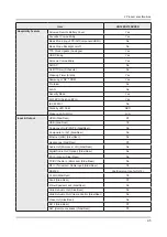
Page 23: ...Micro Dimming N A Wide Color Enhancer Plus Yes Auto Depth Enhancer N A Contrast Enhancer N A Auto Motion Plus N A Film Mode Yes Natural Mode Support N A Audio Dolby Digital Plus Yes Virtual Surround DTS Studio Sound DTS Codec DTS Premium Sound Sound Output RMS 10W Speaker Type 2CH Down Firing Base Reflex Woofer N A Smart TV Samsung SMART TV N A Apps N A Smart Interaction Voice Control N A Converge...

Page 24: ...y No H Browser Compatibility No Samsung LYNK REACH Yes Samsung LYNK REACH Server Compatibility Yes Hospitality Home Menu Yes Bluetooth Music Player Mobile TV No Hospitality Plug Play Easy Set up Yes Power On Mode Yes Hotel Channel List Yes Channel Setup On Off Yes Mixed Channel List ATSC DVB T T2 C S2 Analog Yes My Channel Yes Energy Saving Mode BLU Control Yes Logo Display with Time Out Setting B...

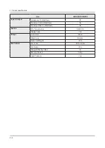
Page 25: ... LED Color RED Wake on LAN WOL N A Input Output HDMI Side Rear 0 1 USB Side Rear 1 0 Component In Y Pb Pr Side Rear No Composite In AV Side Rear No Ethernet LAN Side Rear No Headphone Side Rear 0 1 Audio Out Mini Jack LR Side Rear No Digital Audio Out Optical Side Rear No PC In D sub Side Rear No PC DVI Audio In Mini Jack Side Rear No RF In Terrestrial Cable input Side Rear 1 0 RS232C Yes Common U...

Page 26: ...r Eye Control Side Rear No Door Eye Video In Side Rear No System DTV Tuner Built in DVB T2 C Analog Tuner Yes Design Front Color Black Stand Type Mini Arc Swivel Left Right N A Eco Feature Eco Label EU Eco label Eco Sensor N A Energy Efficiency Class A Mercury Content 0 0 mg Lead Presence Yes ...

Page 27: ...ntents can be purchased separately The part code for some accessories may differ depending on your region Product Code No Product Code No Remote Control AA59 00818A Quick Setup Guide BN68 07310A Batteries AAA x 2 4301 000121 Safety Guide BN68 03019A Power Cord 3903 000950 Image Product Code No Data Cable BN39 00864A Wall mount Adapter BN61 07295A ...

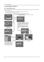
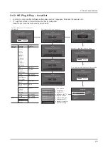
Page 28: ...er On Music Mode Remote Jack Pack External Source Eco Solution Logo Message Cloning REACH Solution Channel Menu OSD Clock HP Management System Security Local Set Change Local Set if Located in North America Latin America and Europe In other regions Please press SKIP button move to the next step Current Localset EU Change Skip Select your language to start the on screen setup English Eesti Suomi Fr...

Page 29: ...Slovenia EU Others Local Set When Local Set is Changed TV will turn off automatically to apply it EU_FRANCE Countries List France Local Set When Local Set is Changed TV will turn off automatically to apply it EU_GER Countries List Austria Germany Switzerland Local Set When Local Set is Changed TV will turn off automatically to apply it NORDIC Countries List Denmark Finland Norway Sweden Local Set ...

Page 30: ...Power on command from main Board to SMPS Power IR Indicator Flashes Panel Back Lights are turned On If no Backlights unplug AC Power Cord unplug 10 pin connector to SMPS plug in AC Power Cord Back light should come on Check Main Board operation for error Power IR Indicator goes off Picture or banner is displayed If nothing is displayed check the LVDS cable ASSY PCB MAIN DC VSS LED PD BD ASSY SPEAK...

Page 31: ...ange the Main Assy or change Function Yes Power On Yes The Remote control act No Cause Remote control has no battery Measure Change the battery Yes Check TP_SW_POWER 3 3V Standby 0V Power on No Cause Sub micom IC did not control the SW_Power Measure Change the Main Assy Yes Check Power of LVDS 13V appear at TP PANEL_VCC 0V to 13V TP PANEL_VCC No Cause There is proble at FET Q202_NFRC or Main IC NT...

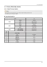
Page 32: ...ons you must change are Type HG32ED470SKXEN Inches 32 PANEL Vendor CORETN Code BN07 01419D Spec JJ032AGH R4 SMPS Vendor POWER Code BN44 00844A Spec P32SF_FPN MAIN ASSY CHASSIS BN91 12216Z ASSY PCB MAIN BN94 07312Z Byte Item 0 Factory Reset 1 Type 32S6AH0JJ 2 Local set EU 3 SW Model HD470 4 BOM Model 470 5 Tuner S_T2C 6 Ch table NONE 4 3 4 Troubleshooting ...

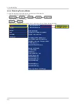
Page 33: ...Advanced menu Option Control Debug SVC ADC WB Advanced T N14LJDEUCB xxxx T N14LJDEUSB xxxx EDID SUCCESS CALIB AV COMP PC HMDI Option xxxx xxxx xxx DTP SDAL NT14L MAIN xxxx x RFS NT14L xxxx K xxxx xx xx KERNEL xxx xxxx Onboot XXXX TCON Version NSP DTVTD HOTEL xxxx Model HG ED470 CIP SUCCESS DRM CRC Factory Data Ver xxx EERC Version xxx NSP BP HAL xxxx NSP AP CNC xxxx NSP AP MM xxxx NSP BP MW xxxx N...

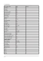
Page 34: ... Front Color N A Lvds Format JEIDA Language_Arabic EU Region PANEURO PnP Language ENG WIFI REGION E OTN Support OFF MediaPlay DLNA TTX ON China HD OFF NT Conversion OFF Num of DTV 1 Num of AV 0 Num of COMP 0 Num of HDMI 1 Num of SCART 1 Num of USB Port 1 Num of RVU 0 Num of Display 2 Num of IPTV 0 Num of RUI 0 TOOLS Support 1849 LNA Support 0 24P 4 Support OFF BD Wise Support OFF Data Service Supp...

Page 35: ...WORK Support Not Support EcoSensor Support OFF 3D Support OFF BT Support OFF BT ADDRESS Not Support HP LINE Headphone Capture Recording Support OFF JAVA Data Service Support OFF African Cinema Mode support OFF Indian Cinema Mode support OFF Cricket Score Game Support OFF Engineer Option Type Of Panel Key Horizontal 5 Way Function Key R_BOTTOM Contents Bar 0 Cable Modulation Standby Led on off OFF ...

Page 36: ...D TYPE LCD_FHD V_ATV CVBS_PORT 2 V_AV1 None V_AV2 None V_COMP1 None V_COMP2 None V_PC None V_SCART1_CVBS CVBS_PORT_3 V_SCART1_RGB ADC PORT 2 V_SCART2_CVBS None V_SCART2_RGB None A_ATV SIF A_DTV DECODER A_AV1 AUIN0 A_AV2 None A_COMP1 None A_COMP2 None A_PC None A_SCART1 AUIN0 A_SCART2 None A_DVI None A_HDMI None A_Media DECODER USING_PSI_UPDATE FAST LOGO DELAY 0 NUM OF PANEL KEY 6 4 7 4 Troubleshoo...

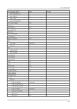
Page 37: ...m 0x0000 Fast Boot in Production OFF USB Serial OFF Eeprom Reset EER Reset 0 NVR ALL Clear OFF ECO IC TYPE None Info Link Server Type operating Info Link Country None TTX Group UserOSD Visual Test MediaPlay DB OPTION_SUM OTN Server Type operating OTN Test Server OFF SWU Reset SWU Duration OFF SWU Fail Test OFF SWU_Diag_Code OPTION_NUM Num of ATV 1 Num of SVIDEO Num of PC Num of DVI 4 8 4 Troublesh...

Page 38: ...D CONTROL OFF RM Server Type Operationg RTS mode 0 PSA FKP Download1 FKP Download2 LMK threshold 0 Low threshold 0 High threshold 0 CSB ON CLB ON EEPG Enable OFF FAnet Thread 5 UNIQUE TRIPLET ON Hotel Option Hospitality Mode SI Vendor Power On Power On Channel Last Saved Power On Channel Num Power On Channel Type Power on Volume Last Saved Power on Volume Num Min Volume 0 Max Volume 100 4 9 4 Trou...

Page 39: ... Off Menu Display On TOOLS DISPLAY ON CHANNEL MENU DISPLAY OFF Panel Button lock Unlock Lock OnlyPower Menu Source Home Menu Display ON Home Menu Editor Home Menu Auto Start ON Clock Clock Typ OFF Local Time Standalone Manual TTX Interactive Manual TTX Auto Time Channel Type Time Channel Num MUSIC Mode Remote Jack Pack Priority HDMI 1 HDMI Option HDMI External Source USB Pop up Screen Default Exte...

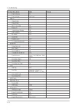
Page 40: ...go DL Logo Display Time Cloning Clone TV to USB Clone USB to TV Setting Auto Intialize OFF REACH Solution REACH 3 0 OFF Ticker OFF Reach server Version 0 Security Password Input Password Setting Password Reset Security Mode USB HDMI TTX Security System Self Diagnosis for TV Self Diagnosis for HTV SW Upgrade Service Pattern OFF Sound Bar Out OFF Contact Samsung Standby LED ON TV Reset 4 11 4 Troubl...

Page 41: ...ier Mute OFF Speaker Delay Normal 0 Wiselink Delay Menu 0 Pilot Level High Thld 0x13h Pilot Level Low Thld 0x09h Pilot_Phase_diff_on_THR OFF FM Prescale 0X2Eh AM Prescale 0x1Ah NICAM Prescale 0x1Dh AMP Model NTP7414 Amp Volume 0xc5h Amp Scale 0x6bh Amp Check Sum 0x1E23D3A9 SubWoofer Support 0 Woofer Type 0 Woofer Volume 0xcbh Woofer Scale 0x8ah Woofer Check Sum NONE Woofer Local Check Sum NONE Amp...

Page 42: ...SNR High Thld 32 Carrier2 SNR Low Thld 17 Audio IP Test Ready SRS Tuning Param 0 TruBass CheckSum 0 Mic Scale 0 India Sound OFF Wall Filter Type 0 SAP High Thld 9 SAP Low Thld 7 Bottom CheckSum 0 Bottom Local CheckSum 0 MFM Option PDD 1670 A_Dimming_Support OFF UnderDriver_Switch OFF Debug Factory Menu Name Data Range Spread Spectrum DDR Margin ND ADJ Support 0 MICOM POWER OFF 0 RF Mute Time 6ms C...

Page 43: ...uner Status SVC Factory Menu Name Data Range Test Pattern Pattern Sel Off LOGIC Pattern Sel LOGIC Level Sel FRC Pre Test Pattern 0 FRC Post Test Pattern 0 SOC TCON Test Pattern 0 SOC TCON Test Pattern 0 SOC TCON Patten Level 0 SOC TCON FRC Patten 0 HDMI WB Pattern 0 HDMI Pattern Sel 0 PANEL DISPLAY TIME 6Hr SVC Info 0 Delete S N Failure Upgrade Smart Hub Reset 0 ER Count LOG Self Diagnosis IPERF S...

Page 44: ... ADC AV Calibration Success Comp Calibraion Success PC Calibration Success HDMI Calibration Success ADC Result 1st_Y_GH 0 1st_Y_GL 0 1st_Cb_BH 0 1st_Cb_BL 0 1st_Cr_RH 0 1st_Cr_RL 0 2nd_R_L 134 2nd_G_L 134 2nd_B_L 134 2nd_R_H 49 2nd_G_H 49 2nd_B_H 49 White Balance R Offset 128 G Offset 128 B Offset 128 R Gain 124 G Gain 128 B Gain 149 WB_W2_R_Offset 128 4 15 4 Troubleshooting ...
Page 45: ... OFF R1_Gain 512 B1_Gain 512 G1_Gain 512 R2_Gain 512 B2_Gain 512 G2_Gain 512 R3_Gain 512 B3_Gain 512 G3_Gain 512 R4_Gain 512 B4_Gain 512 G4_Gain 512 R5_Gain 512 B5_Gain 512 G5_Gain 512 R6_Gain 512 B6_Gain 512 G6_Gain 512 R7_Gain 512 B7_Gain 512 G7_Gain 512 R8_Gain 512 B8_Gain 512 G8_Gain 512 R9_Gain 512 B9_Gain 512 G9_Gain 512 R10_Gain 512 4 16 4 Troubleshooting ...
Page 46: ...Factory Menu Name Data Range B10_Gain 512 G10_Gain 512 Advanced 4 17 4 Troubleshooting ...

Page 47: ...n before adjusting the White Balance Color Calibration Adjust Specification Source Setting Mode Pattern Use Equipment HDMI 1280 x 720 60 Hz Pattern 24 Chess Pattern CA210 Master MSPG925 Generator Chess Pattern Use other equipment only after comparing the result with that of the Master equipment Input mode Calibration Pattern CVBS IN Model_ 1 Perform in NTSC B W Pattern 24 Lattice Component IN Mode...

Page 48: ...u 7 You can see the change of the AV Calibration status from Failure to Success 8 Method of Color Calibration HDMI Apply the 720p Lattice N0 6 pattern signal to the HDMI1 DVI IN port 1 Press the Source key to switch to HDMI1 mode 2 Enter Service mode 3 Select the ADC menu 4 Select the HDMI Calibration menu 5 In HDMI Calibration Off status press the key to perform Calibration 6 When Calibration is ...

Page 49: ...Select 2 ADC WB menu Select 3 White Balance menu Option Control Debug SVC ADC WB Advanced ADC ADC Result White Balance MGA Low Light Sub Brightness R offset G offset B offset Hight Light Sub Contrast R gain G gain B gain 4 20 4 Troubleshooting ...

Page 50: ...d version When software is upgraded video and audio settings you have made will return to their default factory settings We recommend you write down your settings so that you can easily reset them after the upgrade 4 5 1 Main SW Upgrade You need USB including update file 1 http displaysolutions samsung com resources downloadCenter method list save T NT14LDEUCB file in USB Store the SW program name...

Page 51: ...ate files Yes No Update now A new software version is available Update from version 0000 to version 08147 Last checked for update 1 1 2015 10 02 am Yes No Don t turn off the TV or disconnect the power cable until the update finishes Update now Updating produce Softwate Your product will turn itself off and on again automatically after completing update 23 4 22 4 Troubleshooting ...

Page 52: ... program named 1 SubMicomEU bin in a USB memory stick SubMicom Connect the USB memory stick 2 USB memory stick Access the factory mode Select the 3 SVC menu Option Control Debug SVC ADC WB Advanced Select the 4 UPGRADE menu Self Diagnosis Info Upgrade Reset OPTION_HDMI DVB CI TestPattern Other Setting SVC Panel 4 23 4 Troubleshooting ...

Page 53: ...SB Upgrade 0 Fuction Upgrade Failure Eco Data USB Upgrade 0 FRC3D FW Upgrade SC ADK Upgrade Failure FRC3D LD Upgrade 0000 SC MBR Upgrade Failure Camera Upgrade Mic Upgrade ON CPLD USB Download JP MICOM UPGRADE Failure DP MICOM UPGRADE Failure Jump Upgrade Failure Click the 6 Enter button Click the 7 Right button on the remote control Wait for upgrade complete about 5 minutes SUBMICOM UPGRADE Ready...

Page 54: ...tion PDP Option Hotel Option Shop Option Asia Option LFD Option Config Option Select 2 EDID ON OFF and push button of remote control then you can see the change of state OFF to ON EDID ON OFF ON Select 3 EDID WRITE ALL and push button of remote control EDID WRITE ALL Success 4 25 4 Troubleshooting ...

Page 55: ...5 1 5 Wiring Diagram 5 Wiring Diagram 5 1 Wiring Diagram Main Board T CON SMPS SPEAKER SPEAKER Function CN202 CN1203_HD FHD CN403 CN302 ...

Page 56: ...PW 3 A19V_PW 8 DGND 4 DGND 9 A19V_PW 5 A19V_PW 10 DGND 2 CN1202_HD to Panel 1 PANEL 13V_PW 16 EVEN_TXCLK _LVDS 2 PANEL 13V_PW 17 EVEN_TXCLK _LVDS 3 PANEL 13V_PW 18 DGND 4 PANEL 13V_PW 19 EVEN_TX2 _LVDS 5 PANEL 13V_PW 20 EVEN_TX2 _LVDS 6 DGND 21 GND 7 DGND 22 EVEN_TX1 _LVDS 8 DGND 23 EVEN_TX1 _LVDS 9 TCON_WP 24 DGDN 10 LVDS_FORMAT 25 EVEN_TX0 _LVDS 11 NC 26 EVEN_TX0 _LVDS 12 DGND 27 DGND 13 EVEN_TX...

Page 57: ...V_USB1_PW 3 USB1_DP _USB 2 USB1_DM _USB 4 GND 11 CN1301_CI PCMCIA 1 GND 35 GND 2 EXT_DATA 3 36 PCM_CD1 3 EXT_DATA 4 37 TSO_DATA 3 4 EXT_DATA 5 38 TSO_DATA 4 5 EXT_DATA 6 39 TSO_DATA 5 6 EXT_DATA 7 40 TSO_DATA 6 7 PCM_CE1 41 TSO_DATA 7 8 EXT_ADDR 10 42 PCM_CE2 9 PCM_OE 43 NC 10 EXT_ADDR 11 44 PCM_IORD 11 EXT_ADDR 9 45 PCM_IOWR 12 EXT_ADDR 8 46 CH_START 13 EXT_ADDR 13 47 CH_DATA 0 14 EXT_ADDR 14 48 ...

Page 58: ...g Diagram 12 CN401_SC 1 SC_SR_OUT 12 NA 2 SC_SR_IN 13 DGND 3 SC_SL_OUT 14 DGND 4 DGND 15 SC_R 5 DGND 16 SC_FB 6 SC_SL_IN 17 DGND 7 SC_B 18 DGND 8 IDENT_SC 19 SC_CVBS_OUT 9 DGND 20 SC_CVBS_IN 10 NA 21 DGND 11 SC_G ...

Page 59: ...5 Wiring Diagram 5 3 Connector Functions Connector Function CN202 CNM803 Supply main power and dimming signal from IP Board to Main Board CN1202_HD T CON The LVDS signal transfered from Main Board to Panel ...

Page 60: ...ring Diagram 5 4 Cables USE Main SMPS Main T CON LEAD CONNECTOR ASSY CABLE P FFC Code BN39 01885X BN96 35954A Photo NOTE The code number of cable Lead connector can be changed see Exploded Views and Parts List ...

Reviews: