Schematic Diagrams
7-4
Samsung Electronics
This Document can not be used without Samsung’s authorization.
1) F/B terminal of PQIZ1 determines output duty cyle.
2) C-E (Collector-Emitter) of PQIZ1 and F/B potential of PQIZ1 are same.
7-2-3 Internal Block Diagram (Internal Block Diagram of S.M.P.S Circuit)
Smoothing
Circuit
Rectified Circuit
Line Filter
Power IN
(230V)
Noise
Removal
(SNUBBER)
PWM Control
Circuit
(ICE2B765)
Converter
Voltage
Detection
Circuit
3.3V Rectified
Smoothing Circuit
5V Rectified
Smoothing Circuit
12V Rectified
Smoothing Circuit
3.3V Rectified
Smoothing Circuit
5V Rectified
VoltageCircuit (x3)
12V Rectified
VoltageCircuit
O
U
T
P
U
T
(X2)
Fig. 7-4
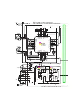
(d) Feedback Control Circuit
PPDD2
3.3V
ICIS01(ICE2B765P)
ICIS02
ICIS03
TRANS(PTISD1)
TCIS05
LIS31
5.8V
CIS31
CIS38
RIS35
RIS36
RIS31
RIS32
RIS33
CIS39
Fig. 7-3
Summary of Contents for DVD-SH853
Page 8: ...Precautions 1 6 Samsung Electronics MEMO ...
Page 16: ...Product Specification 2 8 Samsung Electronics MEMO ...
Page 23: ...Samsung Electronics 4 1 4 Trouble Shooting 4 2 4 45 4 1 Trouble Shooting 4 2 Software Update ...
Page 88: ...5 18 Samsung Electronics Exploded Views and Parts List MEMO ...
Page 90: ...PCB Diagrams 6 2 Samsung Electronics 6 1 Wiring Diagram ...
Page 91: ...PCB Diagrams Samsung Electronics 6 3 6 2 Main PCB COMPONENT SIDE ...
Page 95: ...PCB Diagrams Samsung Electronics 6 7 CONDUCTOR SIDE ...
Page 98: ...PCB Diagrams 6 10 Samsung Electronics CONDUCTOR SIDE ...
Page 99: ...PCB Diagrams Samsung Electronics 6 11 6 5 Front AV PCB COMPONENT SIDE CONDUCTOR SIDE ...
Page 100: ...PCB Diagrams 6 12 Samsung Electronics 6 6 Front PCB COMPONENT SIDE CONDUCTOR SIDE ...


