Samsung DSB-4700F Instructions For Use Manual Download Page 12

21

DSB-4700F

20

D

I

G

I

T

A

L


S

A

T

E

L

L

I

T

E


R

E

C

E

I

V

E

R

DSB-4700F

1.1 LNB Setting

You can select the satellite and  LNB setting conditions to
execute channel search and you can alter the settings for 
22KHz tone. The parameters set in this menu are needed for
programming the channels for the “

Auto scanning

” and

Manual scanning

”. 

The necessary information can be found at your antenna and
LNB brochures, or you can ask your dealer.

● 

Select LNB power supply “

On

”.

● 

Select the desired satellite name.

● 

Select the LNB type (frequency).

● 

Select the DiSEqC Mode 
(Off, DiSEqC A, DiSEqC B, DiSEqC C, DiSEqC D, Tone Burst A, Tone Burst B)

● 

Select the switch 0/12V (“

0V

” or “

12V

”)

If you are using a Positioner, select Positioner DiSEqC1.2 (“

Yes

” or “

No

”)

22KHz:

In case you are using a dual LNB or two antennas connected to a 22KHz tone 
switch box, with the 22 KHz tone switch (“

On

”, “

Off

” or “

Auto

”) you can switch 

between both LNB or antennas.

0/12V:

When you use two LNBs or antennas is switched to 0/12V, select what LNB and 
antenna are used enable or disable. 0/12V terminal is located on the rear of STB.  

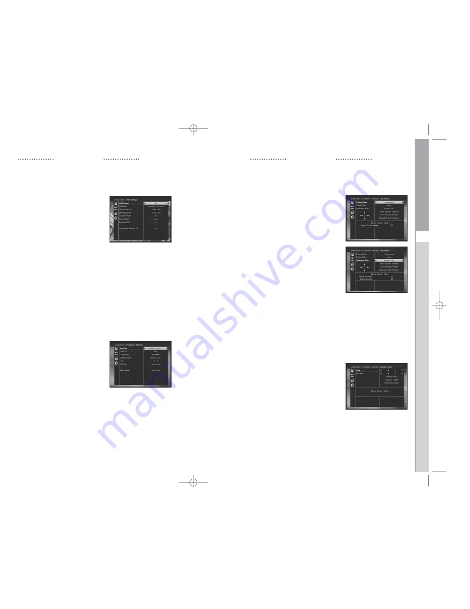
1.2 Positioner Setting

If you have a DiSEqC 1.2 motorized system which is fully
compatible with DiSEqC1.2, then you can take advantage 
of the DiSEqC 1.2 functions available.

● 

Select Satellite.

● 

Select any transponder from above satellites and 
check out the Frequency, Symbol Rate, FEC and Polarity.

In case problems arise, ask your dealer. 
Sometimes this transponder may not exist due to broadcasting. 
It is better to select main transponder among them for the 
desired satellite.

● 

Select from Menu Mode:

User

” mode : 

Enables control of basic positioner function
recommended for beginners. General user uses “

User

” mode.

Installer

” mode :  This is used to search for the position of a satellite manually.

OPERATING THE  RECEIVER

OPERATING THE  RECEIVER

1.2.1 User Mode

● 

Select

Driving Mode

:

You have an option to choose the positioner’s movement type:

Continuous, Step

or 

Time

.

● 

Select

Positioner Slot

:

When a Satellite position is set with the positioner which 
doesn't have enough slots and the default slot number in 
this menu is bigger than a number of slots in a positioner, 
Positioner slot in menu can be changed and fit to the number 
of slot in a positioner for a Satellite.

● 

Position the antenna with north, south, east and west and 
use the

key to drive motor.

key drives to west,

key drives to east,

key drives to north and

key drives 

to south.

● 

If you finished driving of motor, select “

Store current Position.

and press

OK

key, to reset new driving motor.

N

No

otte

e  

:

The level indicated in the “Signal Status” is only for 

reference. The signal quality may be adequate even 
though the level indicated is not maximum.

● 

Go to Stored Position.

When the stored position is reached then screen displays “

Stop

”, you can now continue 

with the further operations.

● 

Select the Calculate Sat Positions to recalculate the satellite position and

OK

key.

1.2.2 Installer Mode

After checking the positioner’s state, installer should use this menu. 
He should set the “

Disable Limits

” before using User mode.

● 

Select the Drive Motor 

West/East and use the

keys 

to drive motor.         

key drives to west and

key drives to east.      

● 

Select “

Enable Limit

”, in order to enable “

Set Limit

”.

● 

Select “

Disable Limit

”, in order to disable “

Set Limit

”.

● 

Select “

Reset Positioner

” and 

OK

key to reset positioner.

0419  MF68-00325A_Eng    4/19/04    5:11  PM    Page  20

Summary of Contents for DSB-4700F

Page 1: ...Instructions foruse REV 1 0 325A DSB 4700F DIGITAL SATELLITE RECEIVER DIGITAL SATELLITE RECEIVER 325A_Eng 4 19 04 5 11 PM Page b ...

Page 2: ...1 DSB 4700F Warning Important Safety Instructions 325A_Eng 4 19 04 5 11 PM Page d ...

Page 3: ...n to perform safety checks to determine that the product is in a safe operating condition This device complies with part 15 of the FCC Rules Operation is subject to the following Two Conditions 1 This device may not cause harmful interference and 2 This device must accept any interference received including interference that may cause undesired operation Warning Important Safety Instructions Thank...

Page 4: ...ct the interference by one or more of the following measures Reorient or relocate the receiving antenna Increase the separation between the equipment and receiver Connect the equipment into an outlet on a circuit different from that to which the receiver is connected Consult the dealer or an experienced radio TV technician for help door Antenna Grounding ure the antenna is properly grounded to pro...

Page 5: ...AUDIO LAYER I II MONO DUAL STEREO AND JOINT STEREO AUDIO MODE 32 44 1 AND 48 KHz SAMPLING FREQUENCIES VOLUME CONTROL AND MUTE FUNCTION THROUGH REMOTE CONTROL UNIT CONTENT Warning Important Safety Instructions 1 General Features 7 Connecting Your STB 8 Description 10 Front Panel 10 Rear Panel 11 Remote Control Unit 12 Basic Functions 14 Operating The Receiver 19 Main Menu 19 1 Installation 19 1 1 L...

Page 6: ...ER TO TV To connect the receiver with your television you can follow two methods through RF cable and through to RCA cable Connect the RF cable to the terminal marked TV at the rear panel of STB and its other end to the TV RF input socket In the case of connecting your TV through RCA cable connect the Receiver Terminal marked Video to the TV Port NECTING YOUR ANALOG RECEIVER To facilitate the user...

Page 7: ...nect any external video and audio 8 RF OUT This is used to connect to your TV via RF cable Preset to channel 3 9 ANT IN This is used to connect your local RF channels to your TV through Loop Rear Panel Panel I This key is for turning the receiver on and Standby K This key is for entering and confirming any data to the receiver in the menu system This key is for selecting the item Press while viewi...

Page 8: ...asing or decreasing the volume 19 TIMER This key is for reserving events programs into timer s in EPG If a event is set in timer it will be turned on off automatically based on start end time of event This key activates deactivates timer s in EPG as toggle type After activating EPG screen by pressing EPG key you can select the interesting event program using the keys and keys Then press timer key ...

Page 9: ...key Transponder BASIC FUNCTIONS BASIC FUNCTIONS ay Screen u can view the television program you must perform the installation you will see only menu images at first elevision channels have been programmed you will see the following nner each time you switch channels he RED i key in view mode he channel by pressing NUMERICAL 0 9 keys or keys and select DIO key to move to TV or Radio channel so see ...

Page 10: ...ed on Timer Field of Time Timer Setting 8 Subtitle When the current broadcasting program provides subtitle press the GREEN TEXT key to see the current subtitle language list If Subtitle is available on current program is displayed on the banner after changing program channel or pressing RED i key To change the subtitle language Press the GREEN TEXT key to see the subtitle language List Use the key...

Page 11: ... program BASIC FUNCTIONS OPERATING THE RECEIVER Main Menu After installing your antenna system and STB with appropriate connectors Plug in the AC main power and switch on the receiver Press MENU key to bring up the main menu The LED display will show MENU The following on screen display will appear The sub menu topics will be displayed For the sub menus Installation Channel Organising and Parental...

Page 12: ...his is used to search for the position of a satellite manually OPERATING THE RECEIVER OPERATING THE RECEIVER 1 2 1 User Mode Select Driving Mode You have an option to choose the positioner s movement type Continuous Step or Time Select Positioner Slot When a Satellite position is set with the positioner which doesn t have enough slots and the default slot number in this menu is bigger than a numbe...

Page 13: ...n press the OK key to save data OPERATING THE RECEIVER Load a transponder This option will enable the user to load any transponder from the preprogrammed list available within the receiver N No ot te e Especially on New transponder at Load TR this new transponder can be added into transponder list so that you can use it on Auto Scanning later only if at least one channel is found with this new tra...

Page 14: ...ows uest window ss OK key the receiver will be reset to factory default utomatically his cause your previous settings to be deleted settings and information including channel data will e deleted 2 Channel Organising The Channel Organising menu has seven functions This menu is for removing some channels from channel list which are related with designated Satellite or Transponder And it provides mak...

Page 15: ... then press the OK key to save the set data ete All Channels uest window press OK key to delete all channels EXIT to exit ete Scrambled Channels uest window press OK key to delete scrambled and press EXIT to exit orite Channels mmediately register the present channel to the desired Group n you can register a channel to multiple favorite groups the desired Favorite Group FAV1 FAV9 he FAV key the de...

Page 16: ... different languages OSD languages are available 20 languages To select the desired language menu press keys to change language and press OK The OSD Language Soundtrack Subtitle or EPG will vary according to the selected language ental Lock ental Lock feature sets viewing restrictions and unauthorized access to your STB through the PIN Identification Number which is a 4 digit number ry preset PIN ...

Page 17: ...Mixed or Full Select the Video Signal Type Composite Select the RF Channel CH 3 CH 4 D Setting et the OSD transparency the display time eme and OSD Position OSD Transparency level SD Transparency level from 0 to 100 is made with the numeric keys keys or G keys eys Setting in increment of 1 G keys Setting in increment of 10 his transparency is NOT applied to color scheme with User Defined option di...

Page 18: ...mer using keys from 1 to 15 he keys to choose event repetition you want to reserve very Sunday Every Monday Every Tuesday Every Wednesday hursday Every Friday Every Saturday Once mer is set from EPG screen EPG is displayed on Event Repetition he Numerical 0 9 keys to set the time you want and press the keys to a switch time you want to reserve If set time on Switch on Time is same as one on off Ti...

Page 19: ... Audio cord connected Check connection and correct incorrectly Loudness level 0 Increase loudness on television set Muting active Press the MUTE key Remote Control does not incorrect operation Point remote control operate directly towards the Receiver Batteries dead or inserted Replace batteries or insert correctly incorrectly Poor picture quality Signal strength to low Check all wire connections ...

Page 20: ... t 8 o decoder m decoding MPEG 2 ISO TEC 13818 Transport Stream e and level MPEG 2 MP ML 4 2 2 rate 1 15 Mb s formats 4 3 normal 16 9 widescreen re resolution 720 H x 576 V x 50 fields sec o Decoder m decoding MPEG 1 ISO TEC 11172 3 layer I II o mode MONO DUAL STEREO JOINT STEREO pling frequency 32 44 1 48 kHz A V output RCA JACK VIDEO CVBS AUDIO R L RF modulator Modulator output CH 3 or 4 preset ...

Page 21: ...MEMO MEMO 325A_Eng 4 19 04 5 11 PM Page 38 ...

Page 22: ...MEMO 325A_Eng 4 19 04 5 11 PM Page 40 ...

Reviews: