


34
Ⅲ. ADJUSTMENT
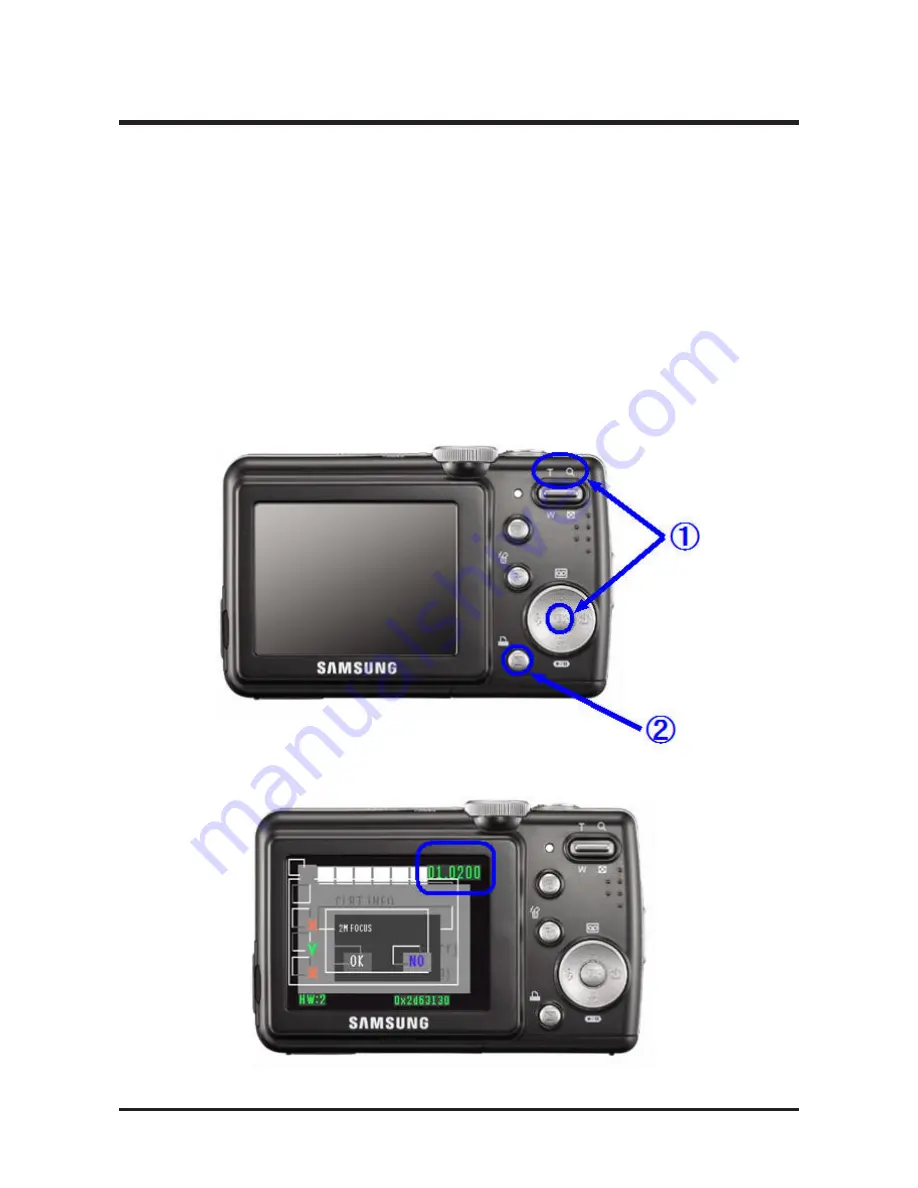
1. FIRMWARE
1) Checking version
1. Remove the memory card from the camera.
2. Connect the AC adapter or a fully charged battery.
3. Turn the camera off.
4. Press and hold the PLAY button for approximately 2 seconds while holding down the TELE button and
the OK button simultaneously.
5. The power is automatically turned on displaying the firmware version on the LCD screen.
Summary of Contents for D85
Page 1: ......
Page 8: ...3 LCD monitor indicator 8 Ⅰ SPECIFICATION Recording mode Image Full Status ...
Page 14: ...Ⅱ EXPLODED VIEW AND PART LIST 14 1 3 1 2 1 3 1 2 1 1 1 4 1 MAIN ASSEMBLY ...
Page 17: ...24 Ⅱ EXPLODED VIEW AND PART LIST 4 FRONT COVER ASSEMBLY 4 1 4 4 4 5 4 2 4 3 4 6 4 7 4 8 ...
Page 49: ...55 Ⅳ PATTERN DIAGRAM 1 PARTS ARRANGEMENT FOR EACH PCB ASS Y 1 MAIN_TOP ...
Page 50: ...56 Ⅳ PATTERN DIAGRAM 2 MAIN_BOTTOM ...
Page 51: ...57 Ⅳ PATTERN DIAGRAM 3 CCD_TOP ...
Page 52: ...58 Ⅳ PATTERN DIAGRAM 4 CCD_BOTTOM ...
Page 53: ...59 Ⅳ PATTERN DIAGRAM 5 STROBE_TOP ...
Page 54: ...60 Ⅳ PATTERN DIAGRAM 6 STROBE_BOTTOM ...
Page 55: ...61 Ⅴ CIRCUIT DIAGRAM 1 MAIN_COACH9S GPIO ...
Page 56: ...62 Ⅴ CIRCUIT DIAGRAM 2 MAIN_COACH9S VOLATGE UI ...
Page 57: ...63 Ⅴ CIRCUIT DIAGRAM 3 MAIN_MEMORY ...
Page 58: ...64 Ⅴ CIRCUIT DIAGRAM 4 MAIN_USB IF ...
Page 59: ...65 Ⅴ CIRCUIT DIAGRAM 5 MAIN_LENS DRIVER ...
Page 60: ...66 Ⅴ CIRCUIT DIAGRAM 6 MAIN_LCD ...
Page 61: ...67 Ⅴ CIRCUIT DIAGRAM 7 MAIN_SYSTEM BLOCK ...
Page 62: ...68 Ⅴ CIRCUIT DIAGRAM 8 MAIN_POWER BLOCK ...
Page 63: ...69 Ⅴ CIRCUIT DIAGRAM 9 MAIN_POWER ...
Page 64: ...70 Ⅴ CIRCUIT DIAGRAM 10 MAIN_AD9920 ...
Page 65: ...71 Ⅴ CIRCUIT DIAGRAM 11 CCD ...
Page 66: ...72 Ⅴ CIRCUIT DIAGRAM 12 CCD Pin Define ...
Page 67: ...73 Ⅴ CIRCUIT DIAGRAM 13 MODE DIAL ...
Page 68: ...74 Ⅴ CIRCUIT DIAGRAM 14 STROBE ...
Page 70: ...76 Ⅵ SERVICE INFORMATION Disassembling the Camera 1 Remove the 2 screws 2 Remove the 2 screws ...
Page 71: ...77 Ⅵ SERVICE INFORMATION 3 Remove the 4 screws 4 Separate the Back Cover ...
Page 74: ...80 Ⅵ SERVICE INFORMATION 9 Remove the 2 screws 10 Separate the PCB from the connector ...
Page 76: ...82 Ⅵ SERVICE INFORMATION 13 Remove the 2 screws 14 Unsolder the battery terminals ...
Page 77: ...83 Ⅵ SERVICE INFORMATION 15 Separate the PCB from the connector 16 Remove the 4 screws ...
Page 78: ...84 Ⅵ SERVICE INFORMATION 17 Separate the Main PCB Bottom of the Main PCB CCD is installed ...
Page 79: ...85 Ⅵ SERVICE INFORMATION Main PCB 18 Remove the 2 screws ...
Page 80: ...86 Ⅵ SERVICE INFORMATION 19 Separate the Flash PCB 20 Remove the 3 screws ...
Page 81: ...87 Ⅵ SERVICE INFORMATION 21 Separate the barrel Assy ...


