background image

Samsung Electronics

Schematic Diagrams

6-5

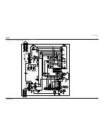
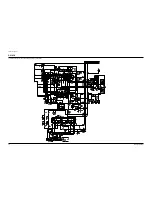
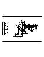
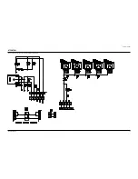
6-5 PIP MODULE

This Document can not be used without Samsung’s authorization.

Summary of Contents for CS29K5MHUX/AAG

Page 1: ... KS7A P REV 1 Model CS29K5MHUX AAG CS29M6MBUX XST DIGITAL TELEVISION RECEIVER CONTENTS Specifications Alignment and Adjustments Exploded Views and Parts List Electrical Parts List PCB Diagram Schematic Diagrams 1 2 3 4 5 6 SERVICE Manual ...

Page 2: ...g Electronics Co Ltd Nov 2004 Printed in Korea AA82 02040A This Service Manual is a property of Samsung Electronics Co Ltd Any unauthorized use of Manual can be punished under applicable International and or domestic law ...

Page 3: ...rmer 2 2 Automatic Degaussing A degaussing coil is mounted around the picture tube so that external degaussing after moving the TV should be unnecessary But the receiver must be properly degaussed upon installation The degaussing coil operates for about 1 second after the power is switched ON If the set is moved or turned in a different direction the power should be OFF for at least 10 minutes If ...

Page 4: ... Voltage may result that Read Cutoff and Read Drive should be red ex IBRM 175 WDRV 110 CDL 250 COLR G B 110 110 110 2 6 White Balance Adjustment 1 Warm up the TV set for at least 30 minutes 2 Enter the Service Mode by pressing the remote control keys in the following sequence Power Off Info Menu Mute Power On 3 Initialize all set data 4 Input a Toshiba pattern 5 Using a probe CA100 do the White Ba...

Page 5: ... 7 When adjusting Screen Voltage and White Balance 1 Screen Voltage and White Balance are related each other Make sure both adjustments are correct 2 Adjust Screen Voltage before White Balance Adjustments Make sure Screen Voltage is correct 3 If White Balance has been readjusted re check Screen Voltage 4 After adjustments are complete check the following If spots appear on the screen after pressin...

Page 6: ...amsung Electronics 2 8 2 Factoy Mode OSD SERVICE T ETPAS0 10XX Deflection Video Adjust1 Video Adjust2 Video Adjust3 Option D2 16 04 02 YC Delay Test Pattern 0 EEPROM Bus Stop Check Sum 0000 Reset 2004 03 08 G2 Adujust 2 8 2 A ADJUST ...

Page 7: ... FIX Depend on the inch CRT Drive FIX Depend on the inch CRT Drive FIX Depend on the inch CRT Drive FIX Depend on the inch CRT Drive FIX Depend on the inch CRT Drive V Amp V Shift H EW H Shift V Linearity V SC H Parabolra Upper Corner Lower Corner Upper Corner 6 Lower Corner 6 H Trapezium Bow Angle EHT Time EHT Threshold EHT Vertical EHT Horizontal EHT Vertical2 EHT Horizontal2 DEFLECTION PAL ET 2...

Page 8: ...28 32 128 128 128 128 128 128 128 128 128 128 Remark FIX FIX FIX FIX FIX FIX FIX FIX FIX FIX FIX FIX FIX FIX V Amp V Shift H EW H Shift V Linearity V SC H Parabolra Upper Corner Lower Corner Upper Corner 6 Lower Corner 6 H Trapezium Bow Angle DEFLECTION NTSC OFFSET ET 2 6 0 14 3 0 0 0 0 0 0 0 0 0 G R 2 6 0 14 3 0 0 0 0 0 0 0 0 0 ...

Page 9: ...X FIX Depend on the inch FIX FIX FIX Depend on the inch CRT Drive Inch Depend on the CRT Inch Depend on the CRT FIX FIX FIX FIX ET 127 127 127 127 127 127 50 55 10 42 1 16 240 255 8 5 4 65 R Cutoff G Cutoff B Cutoff R Drive G Drive B Drive Sub Bright Sub Contrast Sub Color Sub Tint AKB Option BCL Threshold BCL Gain BCL Time Sub Sharpness DVD R Cutoff DVD B Cutoff BCL BCUT Pilot Low NTSC ONLY Pilot...

Page 10: ...rive AMP FIX Depend on the CRT Drive AMP FIX FIX FIX FIX FIX FIX Depend on the mode FIX Depend on the mode FIX Depend on the mode FIX Depend on the mode FIX FIX FIX 2 10 159 159 1 6 4 6 7 3 3 7 15 15 15 255 255 1 3 VSU Melody Volume HB Start HB Stop RF AGC VM Gain VM Delay V_Peaking BLE Tilt BLE Gain BLE Mode BLE Break CTI Gain CTI Coring LTI Gain D EHT Time DCT Ratio LTI Enable VSP Comb ET G R 2 ...

Page 11: ...FIX FIX FIX FIX FIX Depend on the CRT FIX Depend on the CRT FIX Depend on the CRT FIX Depend on the CRT ET 0 1 30 140 50 30 145 10 63 10 24 23 39 5 4 125 122 NR Off Value Gamma Mode Gamma Correction BST StartPoint BST GAIN B DPWL Gain DPWL Start PIP Contrast PIP Tint PIP Color PIP PAL V Pos PIP NTSC V Pos PIP H Pos PIP R Cutoff PIP B Cutoff PIP R Drive PIP B Drive G R 3 1 75 140 50 30 145 10 63 10...

Page 12: ...Language West Europe West Europe Russian West Europe West Europe East Europe Russian Greek Turkey Arabic Farsi Arab Hebrew 8 LNA Off On On Off On Off 9 High Deviate Off Off Off Off On Off 10 TTX On Off On On On On On Off 11 Double TTX Off Off Off Off On Off 12 Tilt Off On Off On On Off 13 Hotel Mode Off Off Off Off On Off 14 Volume Curve Large Curve Large Curve Large Curve Large Curve Large Curve ...

Page 13: ...ness FIX 0 255 20 20 20 28 OSD PIP CONTRAST FIX 0 255 120 120 120 29 OSD PIP BRIGHT FIX 0 255 15 15 15 30 Double TTX H Position FIX 0 255 225 225 31 Standard Equ100 Std BASS FIX 0 255 32 Standard Equ300 Std TREBLE FIX 0 255 13 13 33 Standard Equ1K Music BASS FIX 0 255 14 14 34 Standard Equ3K Music TREBLE FIX 0 255 13 13 35 Standard 10K Movie BASS FIX 0 255 12 12 36 Music Equ100 Movie TREBLE FIX 0 ...

Page 14: ...T POSITION 2 FIX 0 255 249 249 72 3 4CH SLLTHD TV NO NOISE FIX 0 255 73 CH SLLTHD TV NO NOISE FIX 0 255 74 LNA FIX 0 255 110 110 110 75 SLLTHDV TV NO NOISE FIX 0 255 76 VCR TV Noise Level Offset FIX 0 255 77 LNA SW FIX 0 255 78 LMIXOFS FIX 0 255 6 6 31 79 HOUTDEL FIX 0 255 70 70 70 80 Over Modulation Detect FIX 0 255 64 64 81 Over Mod Normal return FIX 0 255 100 100 82 VCR mode detect counter FIX ...

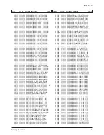
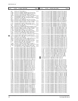
Page 15: ...REG 78R05 TO 220F 4P PL 3 T0087 1203 001543 IC POSI FIXED REG 78R33 TO 220 4P 400MI 3 T0900 1404 001045 THERMISTOR NTC 4 7ohm 15 2900K 35 0mW T 3 P803T 1404 001264 THERMISTOR PTC 4 5OHM 30 20 220V 290V 3 C598 2201 000963 C CERAMIC DISC 1NF 20 400V Y5U TP 9 5X6 3 C598 2201 000987 C CERAMIC DISC 2 2NF 20 400V Y5U BK 12 3 C405 2301 001338 C FILM LEAD OTHER 0 68NF 5 1 6KV BK 28X 3 CR406S 2306 000195 C...

Page 16: ...LAS 4 IC012 1203 001217 IC POSI ADJUST REG 431 TO 92 3P 4 58MIL 4 IC202 1203 001943 IC VOL DETECTOR 7025 TO 92 3P PLASTIC 4 VP801S 1405 000187 VARISTOR 750V 1250A 12 5x7mm TP 4 VX801S 1405 000187 VARISTOR 750V 1250A 12 5x7mm TP 4 R125 2001 000003 R CARBON 330ohm 5 1 8W AA TP 1 8x3 2mm 4 R125 2001 000003 R CARBON 330ohm 5 1 8W AA TP 1 8x3 2mm 4 R125 2001 000005 R CARBON 390ohm 5 1 8W AA TP 1 8x3 2m...

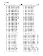
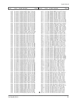
Page 17: ... TP 2 4x6 4m 4 R024 2004 001390 R METAL S 1Kohm 2 1 2W AA TP 2 4x6 4mm 4 R024 2004 001397 R METAL S 4 7Kohm 1 1 2W AA TP 2 4x6 4 4 R024 2004 001889 R METAL S 127Kohm 1 1 2W AA TP 2 5x6 5 4 R024 2004 001891 R METAL S 133Kohm 1 1 2W AA TP 2 5x6 5 4 R024 2004 001983 R METAL S 2 49Kohm 1 1 2W AA TP 2 4x6 4 R024 2004 001984 R METAL S 26 7Kohm 1 1 2W AA TP 2 4x6 4 R024 2004 001986 R METAL S 35 7Kohm 1 1...

Page 18: ...63 C AL 470uF 20 16V GP TP 8x11 5 5 4 C701 2401 002594 C AL 220uF 20 16V GP TP 8x11 5 5 4 C701 2401 002597 C AL 220uF 20 35V GP TP 10x12 5 5 4 C701 2401 002619 C AL 47uF 20 25V GP TP 5x11 5 4 C701 2401 002619 C AL 47uF 20 25V GP TP 5x11 5 4 C701 2401 002619 C AL 47uF 20 25V GP TP 5x11 5 4 C701 2401 002619 C AL 47uF 20 25V GP TP 5x11 5 4 C701 2401 002619 C AL 47uF 20 25V GP TP 5x11 5 4 C701 2401 00...

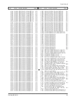
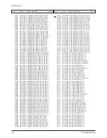
Page 19: ...H S N A 4 EY856 6042 000002 EYELET ID1 5 OD2 L2 8 NI SN BSP3 1 2H S N A 4 EY858 6042 000002 EYELET ID1 5 OD2 L2 8 NI SN BSP3 1 2H S N A 4 EY859 6042 000002 EYELET ID1 5 OD2 L2 8 NI SN BSP3 1 2H S N A 4 EY860 6042 000002 EYELET ID1 5 OD2 L2 8 NI SN BSP3 1 2H S N A 4 EY861 6042 000002 EYELET ID1 5 OD2 L2 8 NI SN BSP3 1 2H S N A 4 EY863 6042 000002 EYELET ID1 5 OD2 L2 8 NI SN BSP3 1 2H S N A 4 EY864 ...

Page 20: ...01 000136 INDUCTOR AXIAL 18UH 10 2534 4 EL01 6042 000002 EYELET ID1 5 OD2 L2 8 NI SN BSP3 1 2H S N A 4 EL02 6042 000002 EYELET ID1 5 OD2 L2 8 NI SN BSP3 1 2H S N A 4 EL03 6042 000002 EYELET ID1 5 OD2 L2 8 NI SN BSP3 1 2H S N A 4 EL04 6042 000002 EYELET ID1 5 OD2 L2 8 NI SN BSP3 1 2H S N A 4 AA41 00552A PCB CONTROL 29M6 25M6 CEM 1 1L A 1 6T 24 S N A 3 D0254 AA32 00012A MODULE REMOCON ORC 50HF2 38KH...

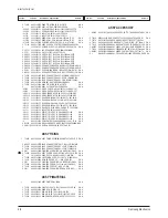
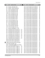
Page 21: ...RUSH S N A 2 T0091 AA94 14077C ASSY PCB MISC A V SIDE 29M6 GOLDRUSH 3 0202 001366 SOLDER WIRE FLUX RS60S D1 2 63Sn 37Pb S N A 3 JA701 3722 001031 JACK PIN 3P 3 6mm 18 AU 3 T0245 AA39 20009D LEAD CONNECTOR ASSY 1P 500 YFH800 01 16 3 T0245 AA39 20068E LEAD CONNECTOR ASSY 8P 500 YBNH025 08 6 3 T0603 AA63 10002A BAND TIE NYLON66 V2 L100 NTR S N A 3 AA97 14906C ASSY AUTO A V 29M6 GOLDRUSH S N A 4C689 2...

Page 22: ...000720 DIODE ZENER MTZJ9 1B 8 57 9 01V 500MW DO 4DZ016 0403 000720 DIODE ZENER MTZJ9 1B 8 57 9 01V 500MW DO 4DZ016 0403 000720 DIODE ZENER MTZJ9 1B 8 57 9 01V 500MW DO 4DZ016 0403 000720 DIODE ZENER MTZJ9 1B 8 57 9 01V 500MW DO 4DZ016 0403 000720 DIODE ZENER MTZJ9 1B 8 57 9 01V 500MW DO 4DZ016 0403 000720 DIODE ZENER MTZJ9 1B 8 57 9 01V 500MW DO 4DZ016 0403 000720 DIODE ZENER MTZJ9 1B 8 57 9 01V 5...

Page 23: ...BON 6 2KOHM 5 1 8W AA TP 1 8X3 2MM 4R125 2001 000924 R CARBON 680OHM 5 1 8W AA TP 1 8X3 2MM 4R125 2001 000969 R CARBON 75OHM 5 1 8W AA TP 1 8X3 2MM 4R125 2001 000969 R CARBON 75OHM 5 1 8W AA TP 1 8X3 2MM 4R125 2001 000969 R CARBON 75OHM 5 1 8W AA TP 1 8X3 2MM 4R125 2001 000969 R CARBON 75OHM 5 1 8W AA TP 1 8X3 2MM 4R125 2001 000969 R CARBON 75OHM 5 1 8W AA TP 1 8X3 2MM 4R125 2001 000969 R CARBON 7...

Page 24: ... TP 7 5x4 0x6 4C2560 2301 000383 C FILM LEAD PEF 10nF 5 50V TP 6x7x3 2mm 4C2560 2301 000383 C FILM LEAD PEF 10nF 5 50V TP 6x7x3 2mm 4C2560 2301 000383 C FILM LEAD PEF 10nF 5 50V TP 6x7x3 2mm 4CV223B 2301 001211 C FILM LEAD PPF 22nF 5 400V TP 20x7x14 4C807 2301 001342 C FILM LEAD PPF 1 5nF 5 800V TP 15x6 5x 4CR404S 2303 001001 C FILM LEAD PPF 22nF 5 630V TP 18x14 5x 4C2560 2305 000237 C FILM LEAD P...

Page 25: ... NI SN BSP3 1 2H S N A 4EY400 6042 000002 EYELET ID1 5 OD2 L2 8 NI SN BSP3 1 2H S N A 4EY401 6042 000002 EYELET ID1 5 OD2 L2 8 NI SN BSP3 1 2H S N A 4EY600 6042 000002 EYELET ID1 5 OD2 L2 8 NI SN BSP3 1 2H S N A 4EY601 6042 000002 EYELET ID1 5 OD2 L2 8 NI SN BSP3 1 2H S N A 4EY602 6042 000002 EYELET ID1 5 OD2 L2 8 NI SN BSP3 1 2H S N A 4EY603 6042 000002 EYELET ID1 5 OD2 L2 8 NI SN BSP3 1 2H S N A...

Page 26: ...4GTT07 AA60 40014A PIN GT ASSY AUTO S N A 4R125 2001 000786 R CARBON 47KOHM 5 1 8W AA TP 1 8X3 2MM 4T0077 AA41 00826F PCB MAIN CS29M6 FR 1 1L 00 1 6T 245 330 S N A 4R075 2001 000066 R CARBON S 10KOHM 5 1 2W AA TP 2 4X6 4 4F101 2901 000299 FILTER EMI ON BOARD 6A UL CSA 9x7 5 3 IC602 BP96 00418A ASSY HEAT SINK P AA62 30182F SCREW TDA72 S N A 4CIS 0205 001154 OIL SILICON G746 S N A 4T0124 1201 001064...

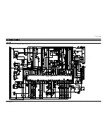
Page 27: ...6 Schematic Diagrams Samsung Electronics Schematic Diagrams 6 1 6 1 MAIN This Document can not be used without Samsung s authorization ...

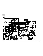
Page 28: ...Schematic Diagrams 6 2 Samsung Electronics 6 2 POWER This Document can not be used without Samsung s authorization ...

Page 29: ...Samsung Electronics Schematic Diagrams 6 3 6 3 CRT This Document can not be used without Samsung s authorization ...

Page 30: ...Schematic Diagrams 6 4 Samsung Electronics 6 4 JACK This Document can not be used without Samsung s authorization ...

Page 31: ...Samsung Electronics Schematic Diagrams 6 5 6 5 PIP MODULE This Document can not be used without Samsung s authorization ...

Page 32: ...Schematic Diagrams 6 6 Samsung Electronics 6 6 CRT 2 This Document can not be used without Samsung s authorization ...

Page 33: ...Samsung Electronics Schematic Diagrams 6 7 6 7 CONTROL This Document can not be used without Samsung s authorization ...

Page 34: ...Schematic Diagrams 6 8 Samsung Electronics 6 8 A V SIDE This Document can not be used without Samsung s authorization ...

Reviews: