10-6
Schematic Diagrams
Samsung Electronics
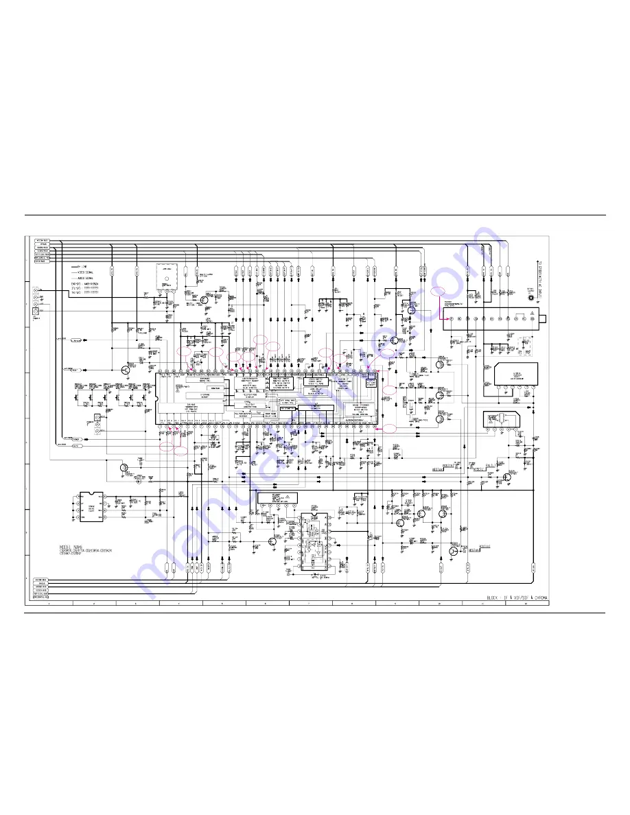
TP07
TP08
TP09
TP10
TP11
TP14
TP12
TP04
TP03
TP02
TP01
TP06
TP05
TP13
10-5 IF & VIF/SIF & CHROMA(MAC ARTHUR)
Page 1: ...EH CS20V10MJOXXSG CS20V10MGOXXSE COLOR TELEVISION RECEIVER CONTENTS Precautions Specifications and IC Data Disassembly and Reassembly Alignment and Adjustment Troubleshooting Exploded View and Parts L...
Page 2: ...Electronics Co Ltd Jul 2003 Printed in Korea AA82 00797D This Service Manual is a property of Samsung Electronics Co Ltd Any unauthorized use of Manual can be punished under applicable International...
Page 3: ...e the last step 2 If the EEPROM or CRT is replaced set PVA to 40 factory mode and set SC as follows 14 inch 0 20 inch 9 21 inch 9 4 2 Factory Service Mode 4 2 1 Procedure for the Adjustment Mode 1 Thi...
Page 4: ...r t i cal S lope 0 63 VS Ver t i cal Shi f t 0 63 VA Ver t i cal Am pl i tud e 0 63 HS Hor i zont al Shi f t 0 63 SC S Cor r ec t i on 0 63 CDL Cat hode Dri ve Level 0 15 STT Sub Ti nt 0 7 SSP Sub Sha...
Page 5: ...4 2 3 Option Bytes In the Service Mode various can be selected via the Option Table Example 1 2 3 4 5 6 7 8 9 10 Option Table xx xx xx xx LNA SYSTEM AUDIO JACK ZOOM AUTO POWER SBL 2nd SIF HOTEL MODE...
Page 6: ...that the power cord is disconnected before replacing any parts 8 To protect against shock hazard use an isola tion transformer 4 3 2 Automatic Degaussing A degaussing coil is mounted around the pic t...
Page 7: ...2 Input a gray scale pattern Use a pattern gen erator PM5518 3 Use the P mode key on the remote control for the STANDARD picture 4 Adjust the Screen VR on the FBT so that the voltage on the oscillosc...
Page 8: ...31m m Vertical Green Belt Fig 4 4 1 2 a Set up 1 Warm up the TV for at least 30 minutes in the Aging Mode OSD White This mode is dis played by entering the following sequence DISPLAY FACTORY FACTORY...
Page 9: ...nd the blue vertical lines in the center area of the screen 5 Turn the both tabs at the same time keeping the angle constant and superimpose the red and blue horizontal line in the center of the scree...
Page 10: ...hat the lion head circle becomes oval 3 Adjust with VSL Vertical Slope so that the bottom margin of the picture is 4 Fig 4 7 4 Adjust with VS Vertical shift so that the top margin of the picture is 4...
Page 11: ...W MULTI REGULATOR 3 3V TO MCU 8V TO MCU I 2C AUDIO A M P TDA 7266S FBT 14 20 21 FSV 14 A 004C S VIDEO AUDIO I 2C VIDEO SI F SA W K9260M U4468B AUDIO IC M C U SP M 802X X X 2 3 2 4 32 21 22 50 53 44 28...
Page 12: ...CS20H4MJ0X AWE KS1A MAC 4 D808 0401 000005 DIODE SWITCHING 1N4148 100V 200mA DO 35 4 D811 0401 000005 DIODE SWITCHING 1N4148 100V 200mA DO 35 4 D901 0401 000005 DIODE SWITCHING 1N4148 100V 200mA DO 3...
Page 13: ...ON 1KOHM 5 1 8W AA TP 1 8X3 2MM 4 R125 2001 000429 R CARBON 1KOHM 5 1 8W AA TP 1 8X3 2MM 4 R125 2001 000429 R CARBON 1KOHM 5 1 8W AA TP 1 8X3 2MM 4 R125 2001 000429 R CARBON 1KOHM 5 1 8W AA TP 1 8X3 2...
Page 14: ...00289 C FILM MPEF 220nF 5 63V TP 5mm 4 C233 2305 000289 C FILM MPEF 220nF 5 63V TP 5mm 4 CR405S 2305 000382 C FILM MPEF 4 7nF 5 400V TP 5mm 4 C901 2305 000412 C FILM MPEF 470nF 5 63V TP 5mm 4 C207 230...
Page 15: ...8 NI SN BSP3 1 2H S N A 4 EY801 6042 000002 EYELET ID1 5 OD2 L2 8 NI SN BSP3 1 2H S N A 4 EY802 6042 000002 EYELET ID1 5 OD2 L2 8 NI SN BSP3 1 2H S N A 4 EY420 6042 000002 EYELET ID1 5 OD2 L2 8 NI SN...
Page 16: ...PVC CU BCWA 300V ROLL 17 0 16mm 22 S N A 3 T0077 AA39 10006X CBF POWER CORD KKP419C KLCE 2F 2 286MT 3 AA61 20284A HOLDER P CORD PP BLK VO KE 002 S N A ASSY P MATERIAL 1 AA92 07726A ASSY P MATERIAL 20V...
Page 17: ...CS30 2201 000304 C CERAMIC DISC 0 001nF 0 25pF 50V NP0 TP 5 CS20 2201 000472 C CERAMIC DISC 0 33nF 5 50V SL TP 8 5x3 5 CS22 2201 000472 C CERAMIC DISC 0 33nF 5 50V SL TP 8 5x3 5 CS07 2201 000982 C CER...
Page 18: ...10K TO 92 T 4 IC803 1203 001217 IC POSI ADJUST REG 431 TO 92 3P 4 58MIL 4 VX801S 1405 000187 VARISTOR 750V 1250A 12 5x7mm TP 4 R906 2001 000005 R CARBON 390OHM 5 1 8W AA TP 1 8X3 2MM 4 R905 2001 0000...
Page 19: ...00376 C CERAMIC DISC 0 22nF 5 50V SL TP 6 3x3 4 C303 2201 000556 C CERAMIC DISC 470PF 10 500V Y5P 6X3 5M 4 C305 2201 000556 C CERAMIC DISC 470PF 10 500V Y5P 6X3 5M 4 C909 2201 000573 C CERAMIC DISC 0...
Page 20: ...1A 3602 000114 FUSE HOLDER 30mohm 4 F801B 3602 000114 FUSE HOLDER 30mohm 4 J192 3812 000219 WIRE NO SHEATH CU TCWA 300V 52mm TAPING 4 J190 3812 000219 WIRE NO SHEATH CU TCWA 300V 52mm TAPING 4 J189 38...
Page 21: ...60 40011A EYELET ID2 0 OD2 8 BST 4 EY420 AA60 40011A EYELET ID2 0 OD2 8 BST 4 EY421 AA60 40011A EYELET ID2 0 OD2 8 BST 4 EY422 AA60 40011A EYELET ID2 0 OD2 8 BST 4 EY423 AA60 40011A EYELET ID2 0 OD2 8...
Page 22: ...70014C 1P TV ASSY ACCESSORY 1 AA92 05543A ASSY ACCESSORY CS21D8STX AWE NIGERIA KS1 2 4301 000120 BATTERY MN 1 5V AA 14 5x50mm 2 AA26 90001C TRANS MATCHING 300OHM 75OHM PAL 40 890 2 AA59 00104A REMOCON...
Page 23: ...75KOHM 5 1 8W AA TP 1 8X3 2MM 3 R301 2001 000016 R CARBON S 1OHM 5 1 2W AA TP 2 4X6 4MM 3 J125 2001 000016 R CARBON S 1OHM 5 1 2W AA TP 2 4X6 4MM 3 R843 2001 000019 R CARBON S 10OHM 5 1 2W AA TP 2 4X...
Page 24: ...1 000342 C FILM PEF 2 2nF 5 50V TP 7 4x3 9x13mm 3 C234 2301 000342 C FILM PEF 2 2nF 5 50V TP 7 4x3 9x13mm 3 C407 2301 000383 C FILM PEF 10nF 5 50V TP 6x7x3 2mm 5mm 3 C227 2301 000445 C FILM PEF 4 7nF...
Page 25: ...2 2 OD2 7 L3 1 NI SN BSP3 1 2H 3 EL502 6042 000001 EYELET ID2 2 OD2 7 L3 1 NI SN BSP3 1 2H 3 EL601 6042 000001 EYELET ID2 2 OD2 7 L3 1 NI SN BSP3 1 2H 3 EL602 6042 000001 EYELET ID2 2 OD2 7 L3 1 NI SN...
Page 26: ...MPER 0 6PHI ROLL TYPE 3 L910 BH39 40362W CBF HARNESS JUMPER 0 6PHI ROLL TYPE 3 J200 BH39 40362W CBF HARNESS JUMPER 0 6PHI ROLL TYPE 3 J117 BH39 40362W CBF HARNESS JUMPER 0 6PHI ROLL TYPE 3 D802 BH39 4...
Page 27: ...10 HIPS HB SILVER 3 AA64 03521A CABINET FRONT 21F10 HIPS HB G4309 SV012P 4 AA81 00106A A S MARKING PAINT P432U DARK GREY TPC 4 HA83 00040B LP MARKING PAINT METALLIC SILVER SV 012 4 HA83 00011A LP RESI...
Page 28: ...000546 DIODE RECTIFIER TVR10G 400V 1 0A DO 41 T 4 T0083 0402 000546 DIODE RECTIFIER TVR10G 400V 1 0A DO 41 T 4 T0083 0402 000546 DIODE RECTIFIER TVR10G 400V 1 0A DO 41 T 4 T0083 0402 000546 DIODE RECT...
Page 29: ...M 5 1 8W AA TP 1 8X3 2MM 4 R125 2001 000734 R CARBON 4 7KOHM 5 1 8W AA TP 1 8X3 2MM 4 R125 2001 000734 R CARBON 4 7KOHM 5 1 8W AA TP 1 8X3 2MM 4 R125 2001 000739 R CARBON 4 7MOHM 5 1 8W AA TP 1 8X3 2M...
Page 30: ...5 4 C701 2401 000025 C AL 100uF 20 16V GP TP 6 3x11 5 4 C701 2401 000050 C AL 10uF 20 16V GP TP 5x11 2 5 4 C701 2401 000050 C AL 10uF 20 16V GP TP 5x11 2 5 4 C701 2401 000262 C AL 100uF 20 160V HR TP...
Page 31: ...TO S N A 4 C810 2301 000192 C FILM PEF 1nF 5 50V TP 5 3x10mm 5mm 4 DZ016 0403 000510 DIODE ZENER MTZJ6 2B 6 2V 5 96 6 27V 500 4 IC012 1203 001217 IC POSI ADJUST REG 431 TO 92 3P 4 58MIL 4 R024 2004 00...
Page 32: ...GRAY 2 CIS AA68 01602B MANUAL USERS ENG W P100G ALL1 B5 KS1A 3 2 CIS AA68 01696B MANUAL USERS ARB W P100G ALL1 B5 KS1A 2 6902 000009 BAG PE HDPE T0 03 L400 W240 TRP 8 2 PE M S N A 2 6801 001063 CARD R...
Page 33: ...AL 10uF 20 50V GP TP 5x11 5 5 C701 2401 000480 C AL 10uF 20 50V GP TP 5x11 5 5 C701 2401 000486 C AL 10uF 20 50V GP TP 6 3x7mm 5 5 C701 2401 000486 C AL 10uF 20 50V GP TP 6 3x7mm 5 5 C701 2401 001026...
Page 34: ...X3 2MM 4 R125 2001 000281 R CARBON 100OHM 5 1 8W AA TP 1 8X3 2MM 4 R125 2001 000281 R CARBON 100OHM 5 1 8W AA TP 1 8X3 2MM 4 R125 2001 000281 R CARBON 100OHM 5 1 8W AA TP 1 8X3 2MM 4 R125 2001 000281...
Page 35: ...M PEF 4 7nF 5 100V TP 10 5x12 5x6 4 C248 2301 000013 C FILM PEF 4 7nF 5 100V TP 10 5x12 5x6 4 C804 2301 000016 C FILM PEF 22nF 5 100V TP 7 2x4 5x9 0mm 4 C109 2301 000016 C FILM PEF 22nF 5 100V TP 7 2x...
Page 36: ...1 5 OD2 L2 8 NI SN BSP3 1 2H S N A 4 EY407 6042 000002 EYELET ID1 5 OD2 L2 8 NI SN BSP3 1 2H S N A 4 EY408 6042 000002 EYELET ID1 5 OD2 L2 8 NI SN BSP3 1 2H S N A 4 EY409 6042 000002 EYELET ID1 5 OD2...
Page 37: ...Y FIXING CS20V10MJ0XXSE KS1A S N A 2 T0076 AA39 20010D LEAD CONNECTOR ASSY 1P 400 YFH800 01 S 2 AA65 30009A CLAMPER CORE FBT ABS V0 BLK S N A 2 AA65 30018A CLAMPER CORE WIRE DONG A NYLON 66 S N A 2 CL...
Page 38: ...le brackets metal cabinets screwheads and control shafts The current measured should not exceed 0 5 milliamp Reverse the power plug prongs in the AC outlet and repeat the test Fig 1 1 AC Leakage Test...
Page 39: ...appear to have overheated or that are otherwise damaged should be replaced with parts that meet the original specifications Always determine the cause of damage or overheat ing and correct any potent...
Page 40: ...and accessible conductive parts examples metal panels input terminals and earphone jacks 6 Insulation Checking Procedure Disconnect the power cord from the AC source and turn the power switch ON Conn...
Page 41: ...rical charges that damage ESDs 5 Use only a grounded tip soldering iron when soldering or unsoldering ESDs 6 Use only an anti static solder removal device Many solder removal devices are not rated as...
Page 42: ...re IF Carrier Sound IF Carrier Color Sub Carrier PAL SECAM D K 1 13 21 69 PAL SECAM D K SECAM K1 38 90 32 40 34 47 SECAM K1 PAL D 2 9 13 57 PAL I 38 90 32 90 34 47 MODEL CI CII CX CK CW CS 14 Inch 20...
Page 43: ...08 LTV817B PHOTO COUPLER SPM802ER TTX English Croatian Romanian Hungarian Polish Czech Bulgarian Russian Portugal IC201S Philips Philips SPM802ERN W O TTX English Croatian Romanian Hungarian Polish Cz...
Page 44: ...4 SPM 802ER Pin 64 X24CO8P Pin 8 KS24C080 Pin 8 U4468B Pin 16 IC TRANSISTOR LA7840 TDA6107Q KA7632 TRANSISTOR TRANSISTOR 2SD1651 2SD1650 2SD2499 KSA614 B C E E B C KSC815 Y KSA539 Y BC548 KTC9014 IC U...
Page 45: ...2 4 MEMO...
Page 46: ...On No Sound Yes No Open the IF Pin of Tuner Check Replace TU01S No Measure the Voltage of Each Pin of TU01S Check IC201S Pins 2 3 See No Video Sound OK See No Sound Video OK Check Replace IC201S Yes N...
Page 47: ...B Lines Check IC802 Pin 8 8V Pin 9 9V Pin 10 5V Check Replace IC801S D801S D802S D803S D804S FP801S Check Replace IC802 KA7632 Check IC201S Pin 1 Stand by 0V Normal 3 3V Check Replace IC201S Check IC2...
Page 48: ...o No Check IC201S Pin 40 CVBS Check Replace IC201S Check IC201S Pins 38 R214 R215 Check IC201S Pin 49 V GUARD Pin 50 Cut off Pin 51 53 R G B out Check Replace IC201S Check IC501 on the CRT PCB Check R...
Page 49: ...V Front assembly Check IC201S Pin 44 Sound Out Check Replace IC201S Check IC601 Pin 3 13 B 10 12 5V Check Replace Q904 IC201S Check IC601 Check Replace IC601 Check IC601 Pins 6 0V Check Replace R814 R...
Page 50: ...OUND L OUT SOUND L IN SOUND R IN FRONT AUDIO IN GND 21 PIN AUDIO IN GND CRT PCB POWER CORD 1 2 3 4 5 180V GND CUT OFF B OUT G OUT R OUT HEAT NC 1 2 3 GND HEAT 180V 1 2 3 4 L OUT R OUT L OUT R OUT CN50...
Page 51: ...9 2 MEMO...
Page 52: ...TP07 TP08 TP09 TP10 TP11 TP14 TP12 TP04 TP03 TP02 TP01 TP06 TP05 TP13 Samsung Electronics Schematic Diagrams 10 1 10 Schematic Diagrams 10 1 IF VIF SIF CHROMA...
Page 53: ...10 2 Schematic Diagrams Samsung Electronics 10 1 1 IF VIF SIF CHROMA WAVEFORMS TP02 TP03 TP04 TP05 TP01 TP08 TP09 TP10 TP11 TP07 TP14 TP13 TP06 TP12...
Page 54: ...Samsung Electronics Schematic Diagrams 10 3 TP15 TP16 10 2 A V RCA SW SUB ASSY TP15 TP16...
Page 55: ...10 4 Schematic Diagrams Samsung Electronics TP15 TP16 TP15 TP16 10 3 A V SCART SW SUB ASSY...
Page 56: ...Samsung Electronics Schematic Diagrams 10 5 TP17 TP18 TP19 TP20 TP21 TP22 TP17 TP18 TP19 10 4 POWER V H DEFLECTION CRT TP20 TP21 TP22...
Page 57: ...10 6 Schematic Diagrams Samsung Electronics TP07 TP08 TP09 TP10 TP11 TP14 TP12 TP04 TP03 TP02 TP01 TP06 TP05 TP13 10 5 IF VIF SIF CHROMA MAC ARTHUR...
Page 58: ...Samsung Electronics Schematic Diagrams 10 7 10 5 1 IF VIF SIF CHROMA WAVEFORMS MAC ARTHUR TP02 TP03 TP04 TP05 TP01 TP08 TP09 TP10 TP11 TP07 TP14 TP13 TP06 TP12...
Page 59: ...10 8 Schematic Diagrams Samsung Electronics TP15 TP16 10 6 A V RCA SW SUB ASSY MAC ARTHUR TP15 TP16...
Page 60: ...Samsung Electronics Schematic Diagrams 10 9 TP15 TP16 TP15 TP16 10 7 A V SCART SW SUB ASSY MAC ARTHUR...
Page 61: ...10 10 Schematic Diagrams Samsung Electronics TP17 TP18 TP19 TP20 TP21 TP22 TP17 TP18 TP19 10 8 POWER V H DEFLECTION CRT MAC ARTHUR TP20 TP21 TP22...