background image

Alignment and Adjustments

Samsung Electronics

4-5

4-3-3 High Voltage Check

CAUTION:  There is no high voltage adjustment on this chassis.

The B+ power supply must be set to +125 volts (Full color  bar input
and normal picture level).

1.   Connect a digital voltmeter to the second

anode of  the picture tube.

2.   Turn on the TV.  Set the  Brightness and

Contrast controls to minimum (zero beam cur-
rent).  

3.   The high voltage should not exceed 27.5KV.

4.   Adjust the Brightness and contrast controls to

both extremes.  Ensure   that the high voltage
does not exceed 27.5KV under any conditions.

4-3-4 FOCUS Adjustment

1.   Input a black and white signal.

2.   Adjust the tuning control for the clearest pic-

ture.

3.   Adjust the FOCUS control for well defined

scanning lines in the center area of the screen.

4-3-5  Cathode Voltage Adjustment

(Screen Adjustment)

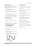
1. Connect CRT socket pin GK  to an oscilloscope

probe.

2. Input a gray scale pattern. (Use a pattern gen-

erator, PM5518)

3. Use the P mode key (on the remote control)

for the STANDARD picture.

4. Adjust the Screen VR (on the FBT) so that the

voltage on the oscilloscope becomes 120+2.5V
(See Fig. 4-1).

4-3-6  Purity Adjustment

1.   Warm up the receiver for at least 20 minutes.

2.   Plug in the CRT deflection yoke and tighten

the clamp screw. 

3.   Plug the convergence yoke into the CRT and

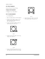
set in as shown in Fig. 4-2.

4. Input a black and white signal.

5. Fully demagnetize the receiver by applying an

external degaussing coil.

6.   Turn the CONTRAST and BRIGHTNESS con-

trols to maximum.

7.   Loosen the clamp screw holding the yoke.

Slide the yoke backward or forward to pro-
vide vertical green belt.  (Fig. 4-3).

8.   Tighten the convergence yoke.

9.  Slowly move the deflection yoke forward,

and adjust for the best overall green screen. 

10. Temporarily tighten the deflection yoke.

11. Produce blue and red rasters by adjusting the

low-light controls.  Check for good purity in
each field.

12. Tighten the deflection yoke.

Fig. 4-1

120   2.5V

+_

GND

      14" :120    2.5V
20, 21" : 120   2.5V

+_

+_  

_

Summary of Contents for CS14Y530X/BWT

Page 1: ...4H40S ATG CS21D90X BWT CS14V5MJ0X CBM COLOR TELEVISION RECEIVER CONTENTS Precautions Specifications and IC Data Disassembly and Reassembly Alignment and Adjustment Troubleshooting Exploded View and Parts List Electrical Parts List Block Diagram Wiring Diagram Schematic Diagrams 1 2 3 4 5 6 7 8 9 10 ...

Page 2: ...g Electronics Co Ltd Aug 2003 Printed in Korea AA82 00885C This Service Manual is a property of Samsung Electronics Co Ltd Any unauthorized use of Manual can be punished under applicable International and or domestic law ...

Page 3: ...dle brackets metal cabinets screwheads and control shafts The current measured should not exceed 0 5 milliamp Reverse the power plug prongs in the AC outlet and repeat the test Fig 1 1 AC Leakage Test 6 Antenna Cold Check With the unit s AC plug disconnected from the AC source connect an electrical jumper across the two AC prongs Connect one lead of the ohmmeter to an AC prong Connect the other le...

Page 4: ...t appear to have overheated or that are otherwise damaged should be replaced with parts that meet the original specifications Always determine the cause of damage or overheat ing and correct any potential hazards 15 Observe the original lead dress especially near the following areas Antenna wiring sharp edges and especially the AC and high voltage power supplies Always inspect for pinched out of p...

Page 5: ...g and accessible conductive parts examples metal panels input terminals and earphone jacks 6 Insulation Checking Procedure Disconnect the power cord from the AC source and turn the power switch ON Connect an insulation resistance meter 500V to the blades of the AC plug The insulation resistance between each blade of the AC plug and accessible conductive parts see above should be greater than 1 meg...

Page 6: ...trical charges that damage ESDs 5 Use only a grounded tip soldering iron when soldering or unsoldering ESDs 6 Use only an anti static solder removal device Many solder removal devices are not rated as anti static these can accumulate sufficient electrical charge to damage ESDs 7 Do not remove a replacement ESD from its protective package until you are ready to install it Most replacement ESDs are ...

Page 7: ...ure IF Carrier Sound IF Carrier Color Sub Carrier PAL SECAM D K 1 13 21 69 PAL SECAM D K SECAM K1 38 90 32 40 34 47 SECAM K1 PAL D 2 9 13 57 PAL I 38 90 32 90 34 47 MODEL CI CII CX CK CW CS 14 Inch 20 Inch 21 Inch AC 100 240V 50 60Hz VHF UHF Telescopic dipole antenna 75 ohm unbalanced type 8 ohm 5W 5W Dual Type 16 ohm 3W Monitor Type Dual Type SYSTEM PAL I UHF PAL I VHF UHF PAL B G SECAM B G PAL B...

Page 8: ...108 LTV817B PHOTO COUPLER SPM802ER TTX English Croatian Romanian Hungarian Polish Czech Bulgarian Russian Portugal IC201S Philips Philips SPM802ERN W O TTX English Croatian Romanian Hungarian Polish Czech Bulgarian Russian Portugal VERTICAL OUTPUT LA7840 TDA7266S IC301 IC601 SOUND AMP 3W x 1CH or 3W x 2CH or 5W x 2CH IC801S KA5Q0765R POWER IC STR IC802 KA7632 CUSTOM REGULATOR 5V 8V 3 3V IC101 U446...

Page 9: ...64 SPM 802ER Pin 64 X24CO8P Pin 8 KS24C080 Pin 8 U4468B Pin 16 IC TRANSISTOR LA7840 TDA6107Q KA7632 TRANSISTOR TRANSISTOR 2SD1651 2SD1650 2SD2499 KSA614 B C E E B C KSC815 Y KSA539 Y BC548 KTC9014 IC UPC574J or KA33V SAW FILTER E C B KSR1012 KSR1010 KSR2010 KTD863 Y KSC2331 Y 1 1 1 G3956M K9260M Fig 2 1 Semiconductor Base Diagrams ...

Page 10: ...2 4 MEMO ...

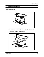
Page 11: ...ics 3 1 Disassembly and reassembly 3 Disassembly and Reassembly 3 1 Back Cover Removal 1 After removing the screws press the tension rib and pull the cabinet backwards 2 To reassemble press the tension rib see diagram ...

Page 12: ...Separate the socket board from the CRT neck 2 Remove the Anode Cap from the CRT 3 Remove the main board by pulling it with both hands Warning The FBT is charged with high voltage Before removing the Anode Cap discharge the voltage through one of the heat sinks on the main board ...

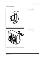
Page 13: ...3 3 Speaker Removal Disassembly and reassembly Samsung Electronics 3 3 1 Remove the speaker by pressing the tension rib 1 Remove the screws 2 Remove the speaker by pressing the tension rib ...

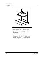
Page 14: ...RT to the front cabi net Lift the CRT 3 Caution Because of the high vacuum and large surface area of the picture tube be careful while handling it 1 Always lift the picture tube by grasping it firmly around the faceplate 2 Never lift the tube by its neck 3 Do not scratch the picture tube or apply excessive pressure Fractures of the glass may cause an implosion ...

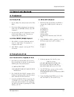
Page 15: ...be the last step 2 If the EEPROM or CRT is replaced set PVA to 40 factory mode and set SC as follows 14 inch 0 20 inch 9 21 inch 9 4 2 Factory Service Mode 4 2 1 Procedure for the Adjustment Mode 1 This mode uses the standard remote control The Service Mode is activated by entering the following remote control sequence 1 DISPLAY FACTORY 2 STAND BY DISPLAY MENU MUTE POWER ON 2 The SERVICE FACTORY m...

Page 16: ...er t i cal S lope 0 63 VS Ver t i cal Shi f t 0 63 VA Ver t i cal Am pl i tud e 0 63 HS Hor i zont al Shi f t 0 63 SC S Cor r ec t i on 0 63 CDL Cat hode Dri ve Level 0 15 STT Sub Ti nt 0 7 SSP Sub Sharpnes s 0 7 PDL PAL Del ay 0 15 NDL NTSC Del ay 0 15 PSR PAL Sub c ol oR 0 23 NSR N TSC Sub c ol oR 0 23 AGC Autom at i c Gai n Cont r ol 0 63 VOL Vol ume pre s et t i ng 0 63 L CO SECAM L V i s i on...

Page 17: ...3 4 2 3 Option Bytes In the Service Mode various can be selected via the Option Table Example 1 2 3 4 5 6 7 8 9 10 Option Table xx xx xx xx LNA SYSTEM AUDIO JACK ZOOM AUTO POWER SBL 2nd SIF HOTEL MODE BKS ON CZ MONO RCA NOR ZOOM 16 9 ON OFF ON OFF ON ...

Page 18: ...e that the power cord is disconnected before replacing any parts 8 To protect against shock hazard use an isola tion transformer 4 3 2 Automatic Degaussing A degaussing coil is mounted around the pic ture tube so that external degaussing after moving the TV should be unnecessary But the receiver must be properly degaussed upon installation The degaussing coil operates for about 1 sec ond after the...

Page 19: ...e 2 Input a gray scale pattern Use a pattern gen erator PM5518 3 Use the P mode key on the remote control for the STANDARD picture 4 Adjust the Screen VR on the FBT so that the voltage on the oscilloscope becomes 120 2 5V See Fig 4 1 4 3 6 Purity Adjustment 1 Warm up the receiver for at least 20 minutes 2 Plug in the CRT deflection yoke and tighten the clamp screw 3 Plug the convergence yoke into ...

Page 20: ...t 31m m Vertical Green Belt Fig 4 4 1 2 a Set up 1 Warm up the TV for at least 30 minutes in the Aging Mode OSD White This mode is dis played by entering the following sequence DISPLAY FACTORY FACTORY 2 Input a Toshiba pattern b Low Light Adjustment 1 Set SBT to 3 5 0 5 fL in the Factory Service Mode with using CA100 See Fig 4 4 2 Adjust RG BG so that the levels are suitable to each local area c H...

Page 21: ...and the blue vertical lines in the center area of the screen 5 Turn the both tabs at the same time keeping the angle constant and superimpose the red and blue horizontal line in the center of the screen 6 Adjust the two tab pairs of the 6 pole magnets to superimpose the red and blue line onto the green Changing the angle affects the vertical lines and rotating both magnets affects the horizontal l...

Page 22: ...that the lion head circle becomes oval 3 Adjust with VSL Vertical Slope so that the bottom margin of the picture is 4 Fig 4 7 4 Adjust with VS Vertical shift so that the top margin of the picture is 4 Fig 4 8 5 Adjust with HS Horizontal Shift so that the lion head pattern and CRT centers are aligned Fig 4 9 6 Adjust HS using the width coil so that the left and right margins of the picture are 5 Al...

Page 23: ... On No Sound Yes No Open the IF Pin of Tuner Check Replace TU01S No Measure the Voltage of Each Pin of TU01S Check IC201S Pins 2 3 See No Video Sound OK See No Sound Video OK Check Replace IC201S Yes No Check Replace IC501 IC201S Check IC201S Pins 40 49 50 See No Sound Video OK ...

Page 24: ...B Lines Check IC802 Pin 8 8V Pin 9 9V Pin 10 5V Check Replace IC801S D801S D802S D803S D804S FP801S Check Replace IC802 KA7632 Check IC201S Pin 1 Stand by 0V Normal 3 3V Check Replace IC201S Check IC201S Pin 1 3 3V Check Replace IC201S µ com Check IC201S Pin 33 H out Check Replace IC201S Q401 Q402 ...

Page 25: ...No No Check IC201S Pin 40 CVBS Check Replace IC201S Check IC201S Pins 38 R214 R215 Check IC201S Pin 49 V GUARD Pin 50 Cut off Pin 51 53 R G B out Check Replace IC201S Check IC501 on the CRT PCB Check Replace IC501 Check Replace R421 R505 HEATER 6 3Vrms D503 CRT G1 pin CRT V999S ...

Page 26: ... V Front assembly Check IC201S Pin 44 Sound Out Check Replace IC201S Check IC601 Pin 3 13 B 10 12 5V Check Replace Q904 IC201S Check IC601 Check Replace IC601 Check IC601 Pins 6 0V Check Replace R814 R815 Yes Yes No Yes Yes 5 5 No TTX No See No Video Check IC201S Check Replace IC201S Yes ...

Page 27: ...ATOR LED 14Y5 PC V0 CLEAR 1 T0059 1 11 6003 001026 SCREW TAPTITE RH B M4 L15 ZPC BLK SWR 1 T0081 S N A 1 12 AA64 01179H KNOB CONTROL 14Y5 ABS HB WHT LB1 1 T0022 1 13 6003 001019 SCREW TAPTITE RH B M4 L12 ZPC BLK SWR 1 T0081 1 14 AA64 00867F DECORATION TOP 14Y5 HIPS VO G4309 1 M0732 2 AA03 10002M CRT COLOR A34KQV42X 0mG 3 20mH 30 0mH 4 1 T0063 2 1 AA60 10050R SCREW ASSY SWRCH18A M5 L31 5 HH WC 4 SC...

Page 28: ...BLK SWR 1 T0081 1 10 AA64 02803A WINDOW RMC LED 20H4 ACRYL CLR 1 T0299 S N A 1 11 6003 001019 SCREW TAPTITE RH B M4 L12 ZPC BLK SWR 1 T0081 1 12 AA96 10146C ASSY SPEAKER 8ohm 5W 3001 000274 350 7 1 S N A 1 13 6003 001019 SCREW TAPTITE RH B M4 L12 ZPC BLK SWR 8 T0081 2 AA03 10002M CRT COLOR A34KQV42X 0mG 3 20mH 30 0mH 4 1 T0063 2 1 AA65 30106A CLAMPER CORE D COIL 14 INCH NYLON 66 V2 2 S N A 2 2 AA6...

Page 29: ... BLK SWR 1 T0081 S N A 1 11 AA64 03277A KNOB CONTROL CS21D9X BWT ABS HB K2901 1 T0022 1 12 6003 001026 SCREW TAPTITE RH B M4 L15 ZPC BLK SWR 1 T0081 S N A 1 13 3001 000274 SPEAKER 5W 8OHM 90DB 160HZ 2 T0082 1 14 6003 001019 SCREW TAPTITE RH B M4 L12 ZPC BLK SWR 8 T0081 2 AA03 10024T CRT COLOR A51KQJ63X H 380mG 2 28mH 22 1 T0063 2 1 3704 001105 SOCKET CRT 11P 20PI 26 5PI NI 1 V999S 2 2 AA60 10050R ...

Page 30: ...4 03118A WINDOW RMC LED 14V5 PC CLR 1 T0299 S N A 1 9 6003 001019 SCREW TAPTITE RH B M4 L12 ZPC BLK SWR 1 T0081 1 10 HOLDER RAIL 1 11 AA96 10146C ASSY SPEAKER 8ohm 5W 3001 000274 350 7 1 S N A 1 12 6003 001019 SCREW TAPTITE RH B M4 L12 ZPC BLK SWR 8 T0081 2 AA91 02164T ASSY CPT A34KQV42X 14 380MG BARE 1 S N A 2 1 AA65 30106A CLAMPER CORE D COIL 14 INCH NYLON 66 V2 2 S N A 2 2 AA60 10050R SCREW ASS...

Page 31: ... T444S AA26 00201A TRANS FBT FCA173B KS1A 1 3 8mH FERRITE 1 3 T401 AA26 50001B TRANS HORIZ DRIVE 7 1mH 102uH 3 T0296 AA27 00053A COIL LINEARITY 193uH DR10X10 C 4 35 7 3 LX801S AA29 30001D FILTER LINE NOISE SQ1913 6 0MH 0 8A 3 RM901 AA32 00015A MODULE REMOCON FRP 3521H31 38KHZ 940MM M 3 T0245 AA39 20620C LEAD CONNECTOR ASSY 9P 500MM YBNH250 09 3 GT301 AA60 40012D PIN GT ASSY T1 6 6 12 5 NYLON66 S N...

Page 32: ...2 R CARBON S 33OHM 5 1 2W AA TP 2 4X6 4M 4 R075 2001 000037 R CARBON S 330OHM 5 1 2W AA TP 2 4X6 4 4 R075 2001 000109 R CARBON S 470OHM 5 1 2W AA TP 2 4X6 4 4 R125 2001 000221 R CARBON 1 2KOHM 5 1 8W AA TP 1 8X3 2MM 4 R125 2001 000241 R CARBON 1 5KOHM 5 1 8W AA TP 1 8X3 2MM 4 R125 2001 000241 R CARBON 1 5KOHM 5 1 8W AA TP 1 8X3 2MM 4 R125 2001 000273 R CARBON 100KOHM 5 1 8W AA TP 1 8X3 2MM 4 R125 ...

Page 33: ...689 2202 000127 C CERAMIC MLC AXIAL 10nF 80 20 25V Y5V 4 C689 2202 000127 C CERAMIC MLC AXIAL 10nF 80 20 25V Y5V 4 C689 2202 000127 C CERAMIC MLC AXIAL 10nF 80 20 25V Y5V 4 C689 2202 000127 C CERAMIC MLC AXIAL 10nF 80 20 25V Y5V 4 C689 2202 000127 C CERAMIC MLC AXIAL 10nF 80 20 25V Y5V 4 C689 2202 000210 C CERAMIC MLC AXIAL 270pF 10 50V Y5P TP 4 C689 2202 000279 C CERAMIC MLC AXIAL 47pF 5 50V SL T...

Page 34: ...LET ID1 5 OD2 L2 8 NI SN BSP3 1 2H S N A 4 EY809 6042 000002 EYELET ID1 5 OD2 L2 8 NI SN BSP3 1 2H S N A 4 EY810 6042 000002 EYELET ID1 5 OD2 L2 8 NI SN BSP3 1 2H S N A 4 EY813 6042 000002 EYELET ID1 5 OD2 L2 8 NI SN BSP3 1 2H S N A 4 EY825 6042 000002 EYELET ID1 5 OD2 L2 8 NI SN BSP3 1 2H S N A 4 EY851 6042 000002 EYELET ID1 5 OD2 L2 8 NI SN BSP3 1 2H S N A 4 EY852 6042 000002 EYELET ID1 5 OD2 L2...

Page 35: ... 3S 720mm ABS UL CSA 2 T0074 AA59 00104J REMOCON TM59 SIM806E 24 L GRAY EX GRAY 2 T0563 AA68 01602B MANUAL USERS ENG W P100G ALL1 B5 KS1A 3 2 T0563 AA68 01795A MANUAL USERS FRE W P100G ALL1 B5 KS1A S N A 2 6902 000009 BAG PE HDPE T0 03 L400 W240 TRP 8 2 PE M S N A 2 6801 001063 CARD REGISTRATION SAMSUNG ENG ARAB MOJ S N A ASSY P MATERIAL 1 AA92 07559A ASSY P MATERIAL 14V5 S N A 2 AA60 40006A PIN S...

Page 36: ... 3704 000103 SOCKET CRT 10P 22 5 14 3 SN ISMS01S BK 3 CN906 3711 003043 CONNECTOR HEADER BOX 4P 1R 2 5MM STRAIGH 3 JS701 3722 000497 JACK PIN 4P 3 4mm SN BLK 3 T0119 AA09 00354A IC MICOM TDA9381 N2 3I SPM 802EEN4 64P 3 3 T801S AA26 00134A TRANS SWITCHING CS21S5T 160V 260V PM2 P 3 T444S AA26 00201A TRANS FBT FCA173B KS1A 1 3 8mH FERRITE 1 3 T401 AA26 50001B TRANS HORIZ DRIVE 7 1mH 102uH 3 T0296 AA2...

Page 37: ... R125 2001 000281 R CARBON 100OHM 5 1 8W AA TP 1 8X3 2MM 4 R125 2001 000281 R CARBON 100OHM 5 1 8W AA TP 1 8X3 2MM 4 R125 2001 000281 R CARBON 100OHM 5 1 8W AA TP 1 8X3 2MM 4 R125 2001 000281 R CARBON 100OHM 5 1 8W AA TP 1 8X3 2MM 4 R125 2001 000281 R CARBON 100OHM 5 1 8W AA TP 1 8X3 2MM 4 R125 2001 000281 R CARBON 100OHM 5 1 8W AA TP 1 8X3 2MM 4 R125 2001 000290 R CARBON 10KOHM 5 1 8W AA TP 1 8X3...

Page 38: ...5 63V TP 7 5x4 0x 4 C2560 2305 000665 C FILM LEAD PEF 100nF 5 63V TP 7 5x4 0x 4 C2560 2305 000665 C FILM LEAD PEF 100nF 5 63V TP 7 5x4 0x 4 C2560 2305 000665 C FILM LEAD PEF 100nF 5 63V TP 7 5x4 0x 4 C2560 2305 000665 C FILM LEAD PEF 100nF 5 63V TP 7 5x4 0x 4 C2560 2305 000665 C FILM LEAD PEF 100nF 5 63V TP 7 5x4 0x 4 C2560 2305 000665 C FILM LEAD PEF 100nF 5 63V TP 7 5x4 0x 4 C2560 2305 000665 C ...

Page 39: ...40014A PIN GT ASSY AUTO S N A 4 GT801 AA60 40014A PIN GT ASSY AUTO S N A 4 GT802 AA60 40014A PIN GT ASSY AUTO S N A 2 T0154 AA95 01751P ASSY SUB PCB CONTROL 14Y5 KS1A AA95 0087 3 0202 000187 SOLDER WIRE FLUX RS60S D1 2 63Sn 37Pb S N A 3 LDC01 0601 000465 LED ROUND GRN 5mm 565 3 C701 2401 000025 C AL 100uF 20 16V GP TP 6 3x11 5 3 SWC01 3404 000176 SWITCH TACT 12V 50mA 120gf 6x6mm SPST 3 SWC02 3404 ...

Page 40: ...3704 000103 SOCKET CRT 10P 22 5 14 3 SN ISMS01S BK 3 CN906 3711 003043 CONNECTOR HEADER BOX 4P 1R 2 5MM STRAIGH 3 JS701 3722 000497 JACK PIN 4P 3 4mm SN BLK 3 T0119 AA09 00354A IC MICOM TDA9381 N2 3I SPM 802EEN4 64P 3 3 T801S AA26 00134A TRANS SWITCHING CS21S5T 160V 260V PM2 P 3 T444S AA26 00201A TRANS FBT FCA173B KS1A 1 3 8mH FERRITE 1 3 T401 AA26 50001B TRANS HORIZ DRIVE 7 1mH 102uH 3 T0296 AA27...

Page 41: ... R125 2001 000281 R CARBON 100OHM 5 1 8W AA TP 1 8X3 2MM 4 R125 2001 000281 R CARBON 100OHM 5 1 8W AA TP 1 8X3 2MM 4 R125 2001 000281 R CARBON 100OHM 5 1 8W AA TP 1 8X3 2MM 4 R125 2001 000281 R CARBON 100OHM 5 1 8W AA TP 1 8X3 2MM 4 R125 2001 000281 R CARBON 100OHM 5 1 8W AA TP 1 8X3 2MM 4 R125 2001 000281 R CARBON 100OHM 5 1 8W AA TP 1 8X3 2MM 4 R125 2001 000290 R CARBON 10KOHM 5 1 8W AA TP 1 8X3...

Page 42: ...5 63V TP 7 5x4 0x 4 C2560 2305 000665 C FILM LEAD PEF 100nF 5 63V TP 7 5x4 0x 4 C2560 2305 000665 C FILM LEAD PEF 100nF 5 63V TP 7 5x4 0x 4 C2560 2305 000665 C FILM LEAD PEF 100nF 5 63V TP 7 5x4 0x 4 C2560 2305 000665 C FILM LEAD PEF 100nF 5 63V TP 7 5x4 0x 4 C2560 2305 000665 C FILM LEAD PEF 100nF 5 63V TP 7 5x4 0x 4 C2560 2305 000665 C FILM LEAD PEF 100nF 5 63V TP 7 5x4 0x 4 C2560 2305 000665 C ...

Page 43: ... 40014A PIN GT ASSY AUTO S N A 4 GT801 AA60 40014A PIN GT ASSY AUTO S N A 4 GT802 AA60 40014A PIN GT ASSY AUTO S N A 2 T0154 AA95 01751P ASSY SUB PCB CONTROL 14Y5 KS1A AA95 0087 3 0202 000187 SOLDER WIRE FLUX RS60S D1 2 63Sn 37Pb S N A 3 LDC01 0601 000465 LED ROUND GRN 5mm 565 3 C701 2401 000025 C AL 100uF 20 16V GP TP 6 3x11 5 3 SWC01 3404 000176 SWITCH TACT 12V 50mA 120gf 6x6mm SPST 3 SWC02 3404...

Page 44: ...YEL SW S N A 4 CIS AA62 00063A HEAT SINK ES DP AA62 30186B S N A 5 AA62 30186B HEAT SINK ES SILVER 171J COVER H S N A 4 CIS AA63 30189A COVER HEATSINK PC ABS T0 8 V0 NTR S N A 3 IC301 AA96 00244M ASSY H S SCREWAA64 00046A LA78040N OIL S S N A 4 CIS 0205 001027 OIL SILICON G746 S N A 4 T0088 1204 002121 IC VERTICAL DEF LA78040N TO220 7P PLA 4 T0081 6003 000335 SCREW TAPTITE RH 2S M3 L8 ZPC YEL SWR ...

Page 45: ...BON 120KOHM 5 1 8W AA TP 1 8X3 2MM 4 R125 2001 000325 R CARBON 120OHM 5 1 8W AA TP 1 8X3 2MM 4 R125 2001 000325 R CARBON 120OHM 5 1 8W AA TP 1 8X3 2MM 4 R125 2001 000429 R CARBON 1KOHM 5 1 8W AA TP 1 8X3 2MM 4 R125 2001 000429 R CARBON 1KOHM 5 1 8W AA TP 1 8X3 2MM 4 R125 2001 000429 R CARBON 1KOHM 5 1 8W AA TP 1 8X3 2MM 4 R125 2001 000449 R CARBON 2 2KOHM 5 1 8W AA TP 1 8X3 2MM 4 R125 2001 000449 ...

Page 46: ...100nF 5 63V TP 7 5x4 0x 4 C2560 2305 000665 C FILM LEAD PEF 100nF 5 63V TP 7 5x4 0x 4 C2560 2305 000665 C FILM LEAD PEF 100nF 5 63V TP 7 5x4 0x 4 C2560 2305 000665 C FILM LEAD PEF 100nF 5 63V TP 7 5x4 0x 4 C701 2401 000025 C AL 100uF 20 16V GP TP 6 3x11 5 4 C701 2401 000025 C AL 100uF 20 16V GP TP 6 3x11 5 4 C701 2401 000025 C AL 100uF 20 16V GP TP 6 3x11 5 4 C701 2401 000025 C AL 100uF 20 16V GP ...

Page 47: ... S N A 4 EY852 6042 000002 EYELET ID1 5 OD2 L2 8 NI SN BSP3 1 2H S N A 4 EY853 6042 000002 EYELET ID1 5 OD2 L2 8 NI SN BSP3 1 2H S N A 4 EY860 6042 000002 EYELET ID1 5 OD2 L2 8 NI SN BSP3 1 2H S N A 4 EY861 6042 000002 EYELET ID1 5 OD2 L2 8 NI SN BSP3 1 2H S N A 4 FIX01 AA37 00001A CONNECTOR FBT FIX PIN JM 3500 CPTTV 0 36 4 FIX02 AA37 00001A CONNECTOR FBT FIX PIN JM 3500 CPTTV 0 36 4 PCB AA41 0084...

Page 48: ...46 C CERAMIC DISC 3 3NF 20 400V Y5U BK 15X 3 CR410S 2303 001015 C FILM LEAD PPF 5 5NF 5 1 6KV BK 29X9 5 3 CX801S 2306 000318 C FILM LEAD PPF 220NF 20 250V BK 22 5 3 C701 2401 002213 C AL 150uF 30 10 450V GP BK 25x35 3 SW801S 3403 001134 SWITCH PUSH 250V 5A DPST ON OFF 3 FP801S 3601 000281 FUSE CARTRIDGE 250V 4A TIME LAG GLASS 5 3 CN906 3711 000628 CONNECTOR HEADER BOX 11P 1R 2 5MM STRAIG 3 JS701 3...

Page 49: ...2W AA TP 2 4X6 4M 4 R075 2001 000037 R CARBON S 330OHM 5 1 2W AA TP 2 4X6 4 4 R125 2001 000221 R CARBON 1 2KOHM 5 1 8W AA TP 1 8X3 2MM 4 R125 2001 000241 R CARBON 1 5KOHM 5 1 8W AA TP 1 8X3 2MM 4 R125 2001 000241 R CARBON 1 5KOHM 5 1 8W AA TP 1 8X3 2MM 4 R125 2001 000273 R CARBON 100KOHM 5 1 8W AA TP 1 8X3 2MM 4 R125 2001 000281 R CARBON 100OHM 5 1 8W AA TP 1 8X3 2MM 4 R125 2001 000281 R CARBON 10...

Page 50: ...2560 2301 000213 C FILM LEAD PEF 220nF 5 250V TP 21 5x11 4 C2560 2301 000233 C FILM LEAD PEF 3 9nF 10 100V TP 5 8x12 4 C2560 2301 000253 C FILM LEAD PEF 39NF 5 100V TP 7 5X4 5X 4 C2560 2301 000289 C FILM LEAD PEF 5 6nF 5 50V TP 7x6x3 5 4 C2560 2301 000289 C FILM LEAD PEF 5 6nF 5 50V TP 7x6x3 5 4 C420 2301 001065 C FILM LEAD PPF 47nF 5 630V TP 19x15 5x 4 C806 2301 001435 C FILM LEAD PPF 1 5nF 5 1 2...

Page 51: ...1 2H S N A 4 EY405 6042 000002 EYELET ID1 5 OD2 L2 8 NI SN BSP3 1 2H S N A 4 EY101 6042 000002 EYELET ID1 5 OD2 L2 8 NI SN BSP3 1 2H S N A 4 EY401 6042 000002 EYELET ID1 5 OD2 L2 8 NI SN BSP3 1 2H S N A 4 EY402 6042 000002 EYELET ID1 5 OD2 L2 8 NI SN BSP3 1 2H S N A 4 EY403 6042 000002 EYELET ID1 5 OD2 L2 8 NI SN BSP3 1 2H S N A 4 EY404 6042 000002 EYELET ID1 5 OD2 L2 8 NI SN BSP3 1 2H S N A 4 EY4...

Page 52: ...Electrical Parts List 7 22 Samsung Electronics MEMO ...

Page 53: ... W MULTI REGULATOR 3 3V TO MCU 8V TO MCU I 2C AUDIO A M P TDA 7266S FBT 14 20 21 FSV 14 A 004C S VIDEO AUDIO I 2C VIDEO SI F SA W K9260M U4468B AUDIO IC M C U SP M 802X X X 2 3 2 4 32 21 22 50 53 44 28 2 3 45 48 38 42 35 2 12 8 S W 2 S W 1 11 P r e A M P PAP103T SYSTEM OPTION R G B FB H OUT TR 3 3 16 5V TO Ver A M P 180V TO C RT Heat TO C RT 13V TO SOUND AMP 8R 2E A 16R 2E A 16R 1E A 8R 1E A KA763...

Page 54: ...SOUND L OUT SOUND L IN SOUND R IN FRONT AUDIO IN GND 21 PIN AUDIO IN GND CRT PCB POWER CORD 1 2 3 4 5 180V GND CUT OFF B OUT G OUT R OUT HEAT NC 1 2 3 GND HEAT 180V 1 2 3 4 L OUT R OUT L OUT R OUT CN501B CN501 CN603 CN701 9 10 11 SOUND R OUT GND FRONT VIDEO IN 21 PIN VIDEO IN 6 7 8 ...

Page 55: ...9 2 MEMO ...

Page 56: ...TP07 TP08 TP09 TP10 TP11 TP14 TP12 TP04 TP03 TP02 TP01 TP06 TP05 TP13 Samsung Electronics Schematic Diagrams 10 1 10 Schematic Diagrams 10 1 IF VIF SIF CHROMA ...

Page 57: ...10 2 Schematic Diagrams Samsung Electronics 10 1 1 IF VIF SIF CHROMA WAVEFORMS TP02 TP03 TP04 TP05 TP01 TP08 TP09 TP10 TP11 TP07 TP14 TP13 TP06 TP12 ...

Page 58: ...Samsung Electronics Schematic Diagrams 10 3 TP15 TP16 10 2 A V RCA SW SUB ASSY TP15 TP16 ...

Page 59: ...10 4 Schematic Diagrams Samsung Electronics TP15 TP16 TP15 TP16 10 3 A V SCART SW SUB ASSY ...

Page 60: ...Samsung Electronics Schematic Diagrams 10 5 TP17 TP18 TP19 TP20 TP21 TP22 TP17 TP18 TP19 10 4 POWER V H DEFLECTION CRT TP20 TP21 TP22 ...

Page 61: ...10 6 Schematic Diagrams Samsung Electronics TP07 TP08 TP09 TP10 TP11 TP14 TP12 TP04 TP03 TP02 TP01 TP06 TP05 TP13 10 5 IF VIF SIF CHROMA MAC ARTHUR ...

Page 62: ...Samsung Electronics Schematic Diagrams 10 7 10 5 1 IF VIF SIF CHROMA WAVEFORMS MAC ARTHUR TP02 TP03 TP04 TP05 TP01 TP08 TP09 TP10 TP11 TP07 TP14 TP13 TP06 TP12 ...

Page 63: ...10 8 Schematic Diagrams Samsung Electronics TP15 TP16 10 6 A V RCA SW SUB ASSY MAC ARTHUR TP15 TP16 ...

Page 64: ...Samsung Electronics Schematic Diagrams 10 9 TP15 TP16 TP15 TP16 10 7 A V SCART SW SUB ASSY MAC ARTHUR ...

Page 65: ...10 10 Schematic Diagrams Samsung Electronics TP17 TP18 TP19 TP20 TP21 TP22 TP17 TP18 TP19 10 8 POWER V H DEFLECTION CRT MAC ARTHUR TP20 TP21 TP22 ...

Reviews: