background image

English_23


C

A

me
RA
 Ope

RATION

ExPosurE

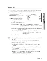
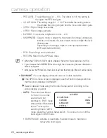
 When the SETUP menu screen is displayed, select ‘EXPOSURE’ by using the 

Function Setup switch so that the arrow indicates ‘EXPOSURE’.
Select a desired mode using the 

Function Setup switch.

brighTnEss : 

 Adjusts the video 

brightness. 

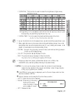
lEns

 :  Using this function, you 

can control the screen 

brightness.

DC/VIDEO : Select Auto Iris Lens.

IRIS SPEED (DC) :  Adjusts the Iris control speed of the DC lens. If the 

control speed is too slow or fast, please use this menu to 

adjust the speed.

Level (VIDEO) :  Adjusts the level of video iris signals; the higher the level, the 

brighter the video looks.

FOCUS ADJ (DC/VIDEO) :  To correctly adjust the focus of LENS, activate 

the focus setup mode located at the bottom of 

each lens menu.

Manual :  Select Manual Lens.


When using VIDEO lens, adjust the lens VR explained below first and set the focus using 'FOCUS 
ADJ' menu.
Some lenses may not work properly, depending on the setting of the BRIGHTNESS LEVEL.
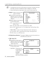
When Using a Video-Type Auto Iris Lens

 Adjust the ALC adjustment terminal on the lens appropriately. In general, set it to AV 
(Average).
  It may not work properly depending on the installed lens. Set the Level VR of the lens to 

the optimal value.

  Set AGC to OFF and adjust the Lens VR to an appropriate brightness.
  Adjust the Lens VR, adjust the BRIGHTNESS, and then check if the screen brightness 

changes properly. Otherwise, adjust the Lens VR again.

※ 

Lens’ level VR may not operate depending on the type of lens.

1.

2.

-

-

M


1)

2)

3)
4)

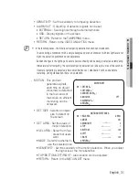
EXPOSURE SETUP

 1. 

BRIGHTNESS


----

---- 

50

  2. 

LENS


DC

  3. 

SHUTTER


  4. 

AGC


HIGH

  5. SSNR4 

ON

  6. 

RETURN


Summary of Contents for Beyond SCB-5003

Page 1: ...Supreme Resolution WDR Camera User Manual SCB 5003 ...

Page 2: ...sung Techwin makes the best to verify the integrity and correctness of the contents in this document but no formal guarantee shall be provided Use of this document and the subsequent results shall be entirely on the user s own responsibility Samsung Techwin reserves the right to change the contents of this document without prior notice Warranty If the product does not operate properly in normal co...

Page 3: ...and correct input power voltage To help you understand this manual thoroughly we ll introduce our model description SCB 5003 SERIES NTSC MODEL PAL MODEL SCB 5003N SCB 5003P MODEL DESCRIPTION SCB 5003X _ SIGNAL SYSTEM N NTSC MODEL P PAL MODEL SIGNAL SYSTEM ...

Page 4: ...zard do not expose this appliance to rain or moisture To prevent injury this apparatus must be securely attached to the floor wall in accordance with the installation instructions WARNING Be sure to use only the standard adapter that is specified in the specification sheet Using any other adapter could cause fire electrical shock or damage to the product Incorrectly connecting the power supply or ...

Page 5: ... objects on the product or apply strong shock to it Keep away from a location subject to excessive vibrationor magnetic interference Do not install in a location subject to high temperature over 55 C low temperature below 10 C or high humidity Doing so may cause fire or electric shock If you want to relocate the already installed product be sure to turn off the power and then move or reinstall it ...

Page 6: ... be disposed of with other household waste at the end of their working life Where marked the chemical symbols Hg Cd or Pb indicate that the battery contains mercury cadmium or lead above the reference levels in EC Directive 2006 66 If batteries are not properly disposed of these substances can cause harm to human health or the environment To protect natural resources and to promote material reuse ...

Page 7: ...apparatus Only use attachments accessories specified by the manufacturer Use only with cart stand tripod bracket or table specified by the manufacturer or sold with the apparatus Unplug this apparatus when a card is used Use caution when moving the cart apparatus combination to avoid injury from tip over Refer all servicing to qualified service personnel Servicing is required when the apparatus ha...

Page 8: ...erview 13 Lens connection 16 16 Connecting to Monitor 16 Connecting to Power 17 Control via RS 485 Interface 18 Using Coaxial Communications camera operation 19 19 Menu Configuration 19 Menu Setup troubleshooting 36 36 Troubleshooting specifications 37 37 Specifications 39 Dimension ...

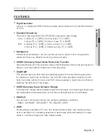
Page 9: ... level and shows a vivid high definition video even in the dark place Day Night This camera has a function that automatically selects the mode that is appropriate for daytime or night time conditions The COLOR mode operates in daytime condi tions to provide optimum colors and B W mode operates in night time conditions to enhance the definition of the image SSDR Samsung Super Dynamic Range If an ob...

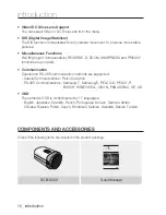
Page 10: ... Communication Coaxial and RS 485 communication methods are supported Coaxial Communications Pelco Coaxitron RS 485 Communications Samsung T Samsung E PELCO D PELCO P BOSCH HONEYWELL VICON PANASONIC GE AD OSD The camera s OSD is complimented by 17 languages English Japanese Spanish French Portuguese Korean German Italian Chinese Russian Polish Czech Romanian Serbian Swedish Danish Turkish Componen...

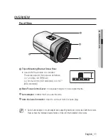
Page 11: ...SO standard or 0 197 ASA standard 2 Back Focus Control Lever It acquires margins for lens adjustments 3 Lens adaptor IInstall this if you use the lens 4 Auto Iris Lens Connector Used to connect Auto Iris Lens plug Auto shutter adaptor c mount adaptor and supporting board are not provided with the camera Please check the installed documentation of tripod for the installation of cameras M 1 4 3 2 ...

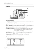
Page 12: ...he video input terminal of the monitor 4 Power input terminal Connect the designated power supplies 5 RS 485 Control Port You can control SETUP MENU through this port by using external controllers like a Remote controller that RS 485 Communication is supported 6 D N Input Port You can switch to Day Night Mode by connecting an external signal to this port 7 MD Output Port Motion detection signals a...

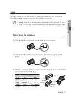
Page 13: ...dirt or fingerprints the picture quality suffers When Using Auto Iris Lens Strip the insulation of the auto iris lens cable 8mm from the end approx 8mm Strip the insulation of the core of the auto iris lens cable to expose a 2mm length approx 2mm Remove the cover of the auto iris lens connector plug and solder the lens cable to the connector pin of the plug LENS Pin No DC VIDEO No 1 Pin Damping Re...

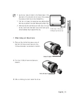
Page 14: ...he focus When Using a C CS Mount lens Sold separately Before installing a lens identify whether the lens to be installed is a C Mount or CS Mount This camera is set for a CS Mount Lens by default To install a C Mount Lens a simple modification is required When Using a CS Mount Lens Remove the protective glass cover at the front of this product and turn the CS Mount Lens clockwise to install it 4 5...

Page 15: ...less than 450g When adjusting the Automatic Level Control ALC of an auto iris lens use Av mode if available If you use the Pk mode the picture brightness may change continuously When Using a C Mount Lens Remove the protective glass cover at the front of this product and turn the C Mount Adapter clockwise to install it Turn the C Mount lens clockwise to install it After combining the lens adjust th...

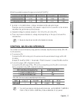
Page 16: ...ries with the instruments refer to the manual supplied with the instrument Only connect the cable when the power is turned off Connecting to Power You can connect power as shown in the following figure Since the power specification supports both AC and DC connect AC 24V 500mA Adaptor or DC 12V 500mA Adaptor POWER VIDEO SCB 5003 Monitor POWER VIDEO ...

Page 17: ... The camera can be controlled by using external controllers like a Remote controller RS 485 Communication 1 To control by PC Connect the RS 485 control port of the camera and the serial cable through an RS 485 converter Example PC Serial Port COM1 Serial Cable RS 485 Converter Camera RS 485Control Port 2 To control using a DVR or System Controller Connect the RS 485 cable TRX TRX to the connection...

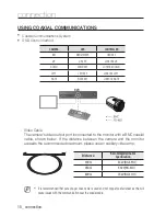
Page 18: ...DOWN KEY JOYSTICK DOWN LEFT LEFT KEY JOYSTICK LEFT RIGHT RIGHT KEY JOYSTICK RIGHT 1 2 3 4 5 6 7 8 9 10 11 12 13 14 15 16 ALARM HDD NETWORK BACKUP REC DVD RECORDE R REC ZOOM MODE FREEZE AUDIO BACKUP ALRAM SEARCH TELE WIDE VIEW PRESET MENU RETURN USB OPEN CLOSE MENU SEARC H MUL TI REC MENU PRESE T GROUP TRACK CAM 1 2 3 4 5 6 7 8 9 0 MON CLOSE OPEN NEAR FAR WIDE TELE PTZ DVR MTX SETUP ESC FUNC ENTER ...

Page 19: ...TDOOR INDOOR MANUAL AWC SET MERCURY EXPOSURE BRIGHTNESS LENS SHUTTER AGC SSNR4 RETURN BACKLIGHT OFF USER BLC HLC WDR SPECIAL DISPLAY COMM ADJ IMAGE ADJ DAY NIGHT DEFOG PRIVACY DIS VIDEO ANALYTICS RETURN EXIT SAVE NOT SAVE RESET Menu Setup Use the Function Setup switch within the camera camera operation POWER VIDEO Function Setup switch ...

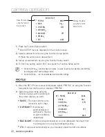
Page 20: ... Setup switch so that the arrow indicates PROFILE Select a desired mode using the Function Setup switch according to the picture display you want BASIC The most common envi ronment is set to meet DAY NIGHT It will be set automatically so it optimizes to the day or night conditions respectively BACKLIGHT It will be set automatically so you can distinguish the object from the background in a severe ...

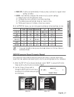
Page 21: ...H WHITE BAL ATW ATW ATW OUTDOOR INDOOR BACKLIGHT OFF OFF USER BLC OFF OFF SSNR4 ON ON ON ON ON DAY NIGHT AUTO AUTO AUTO AUTO AUTO If you select the traffic monitoring mode the shutter will be set to 1 200 sec Noise can be detected at night M SSDR Samsung Super Dynamic Range If an object has a large variance between bright and dark areas it will keep bright areas bright and make selected dark areas...

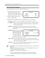
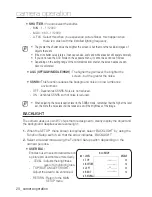
Page 22: ...lly Set White Balance first by using the ATW or AWC mode After that button to MANUAL mode fine tune the White Balance and the Function Setup switch AWC SET To find the optimal luminance level for the current environment point the camera towards a sheet of white paper and press the Function Setup switch If the environment changes readjust it Mercury This is an auto compensation function that optimi...

Page 23: ...the focus setup mode located at the bottom of each lens menu Manual Select Manual Lens When using VIDEO lens adjust the lens VR explained below first and set the focus using FOCUS ADJ menu Some lenses may not work properly depending on the setting of the BRIGHTNESS LEVEL When Using a Video Type Auto Iris Lens Adjust the ALC adjustment terminal on the lens appropriately In general set it to AV Aver...

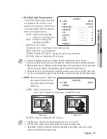
Page 24: ...oise in a low luminance environment OFF Deactivates SSNR4 Noise is not reduced ON Activates SSNR4 so that noise is reduced When adjusting the noise reduction level in the SSNR4 mode remember that the higher the level set the more the noise level will be reduced as will the brightness of the image BACKLIGHT The camera uses our own W7 chips that are designed to clearly display the object and the bac...

Page 25: ...HLC according to the amount of light area in the screen optimize the installation angle for the best HLC performance When dark the HLC is only activated when a bright light exceeding a specifi c size In NIGHT ONLY mode The HLC is not activated in day light or when bright light is not present at night In NIGHT ONLY mode WDR When there are both bright and dark areas at the same time this mode makes ...

Page 26: ...tup switch The entered title appears on the screen Select the position to display the title on the screen by using the Function Setup switch and press the Function Setup switch When the position is determined select END and press the Function Setup switch to return to the DISPLAY menu When the CAM TITLE menu is OFF no title will be displayed on the monitor screen even if you enter one and Numbers ...

Page 27: ...ID Determines the camera s identification number between 0 and 255 BAUD RATE You can select 2400 4800 9600 19200 38400 57600 bps UART MODE You can select NONE EVEN or ODD for the parity bits RET PKT Determines whether to send a command back to the controller device when a communication control command is sent to the camera COAX You can select whether to use COAX communication RETURN Return to the ...

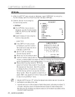
Page 28: ...led the text on the screen does not fl ip If you increase the SHARPNESS level too high the picture may become distorted or noise may appear When you use the PFR function if there is an object near the strong light the color can be missing DAY NIGHT You can display pictures in color or in black and white If the SPECIAL menu screen is displayed use the Function Setup switch so that the arrow indicat...

Page 29: ... a hunting can be caused In this situation it is recommended to use the default setting 30 sec EXTERN Ground to the grounding terminal to allow automatic switching between COLOR and B W Black White COLOR The picture is always displayed in color B W The picture is always displayed in black and white You can turn on or off the burst signal on B W mode If the lens mounted in the camera is different f...

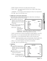
Page 30: ... Red Blue Black White Gray TRANSPARENCY Adds or removes transparency from the masking area SEL POS XPOS YPOS Adjust the size and position of the selected area RETURN Return to the SPECIAL menu DIS Digital Image Stabilizer This function mitigates any picture movement due to external factors such as wind VIDEO ANALYTICS If the SPECIAL menu screen is displayed use the Function Setup switch so that th...

Page 31: ...max of five seconds If camera tampering is detected after some time five sec stabilization will be done before restarting During stabilization there is no detection MOTION This product generates signals each time an object movement is detected in the four areas of the screen so efficient monitoring can be achieved DET SIZE Selects an object size to detect on the screen DET AREA Set the areas of mo...

Page 32: ...gh external terminals OSD Display signals on the screen RETURN Return to the MOTION DET menu RETURN Return to the VIDEO ANALYTICS menu INTELLIGENCE Set the intelligent video detection function SENSITIVITY Set the sensitivity of the motion detection When you adjust the higher level the more sensitive DET SIZE Selects an object size to detect on the screen FENCE SEL FENCE You can select up to 4 FENC...

Page 33: ...exiting the fenced area IN OUT Detects all objects entering and exiting the fenced area RETURN Return to the VIRTUAL FENCE menu COUNT Displays how many times a subject passes over the fence on the screen RETURN Return to the INTELLIGENCE menu APPEAR Detects an object that emerges or disappears from the screen or stays onscreen without movement INDICATOR Outlines an object on the screen in a box wh...

Page 34: ...edge If multiple movements keeps occurring randomly such as scene switching or sudden light changes If an object fixed in the same location keeps moving Moving away from the camera or approaching the camera Little location change on the screen If a moving object approaches the camera If random objects obstruct the view of each other If more than one objects merge or one object divides into multipl...

Page 35: ...Setup switch depending on the camera purpose SAVE Save the current settings and exit the MAIN SETUP menu NOT SAVE Do not save the current settings and exit the MAIN SETUP menu RESET Revert camera to factory settings The language communication and lens settings will remain the same ...

Page 36: ...ge the camera position The image on the screen is dark Adjust the contrast feature of the monitor or DVR If you have an intermediate device set the 75Ω Hi z properly The camera is not working properly and the surface of the camera is hot Check that you have properly connected the camera to an appropriate power source he DAY NIGHT menu does not work Check that AGC of EXPOSURE SETUP menu is OFF The ...

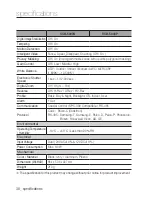
Page 37: ...F1 2 30IRE 0 00003Lux 1sec F1 2 30IRE S N Ratio 52dB AGC off Weight on Video Output CVBS 1 0 Vp p 75Ω composite Lens Type Focus Control Manual Lens Type Manual DC Auto Iris Video IRIS Mount Type C CS Operational On Screen Display English Chinese Korean Japanese German Italian French Spanish Russian Czech Polish Romanian Serbian Swedish Danish Turkish Portuguese Camera Title Off On Displayed 15 cha...

Page 38: ...m Off On 1x 16x Reverse Off H Rev V Rev HV Rev Profile Basic Day Night Backlight ITS Indoor User Alarm 1 Out Communication Coaxial Control SPC 300 Compatible RS 485 Protocol Coax Pelco C Coaxitron RS 485 Samsung T Samsung E Pelco D Pelco P Panasonic Bosch Honeywell Vicon AD GE Environmental Operating Temperature Humidity 10 C 55 C Less than 90 RH Electrical Input Voltage Dual 24VAC 10 12VDC 10 Pow...

Page 39: ...English_39 specifications Dimension Unit mm ...

Page 40: ...MEMO ...

Page 41: ...147 8740 60 FAX 82 31 8018 3745 SAMSUNG TECHWIN EUROPE LTD Samsung House 1000 Hillswood Drive Hillswood Business Park Chertsey Surrey UNITED KINGDOM KT16 OPS TEL 44 1932 45 5300 FAX 44 1932 45 5325 SAMSUNG TECHWIN AMERICA Inc 100 Challenger Rd Suite 700 Ridgefield Park NJ 07660 Toll Free 1 877 213 1222 Direct 1 201 325 6920 Fax 1 201 373 0124 www samsungcctvusa com SALES NETWORK ...

Reviews: