background image

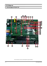
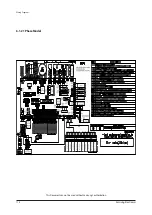
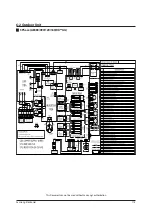
PCB Diagram

Samsung Electronics

101

No.

Local

Function

Description

1

TB-A

MAIN POWER

DAPC 3013-2P BLK

2

TB-A1

BOOSTER&IMMERSION HEATER

DAPC 3013-2P BLK

3

TB-B

EXTERNAL CONTROL

BR-1000C2-26P BLK

4

CNP003

MC-COMMON

YTR250

5

CNP501

3-WAY VALVE

YW396-05AV WHT

6

CNP401

HEATER THERMOSTAT

YW396-03AV WHT

7

CNP002

MC2-A

YTR250

8

CNP001

MC1-A

YTR250

9

CNS002

WATER PUMP SIG/GND

BR-7623C-2P BLK

10

CNS001

WATER PUMP SIG/GND

SMW250-03 WHT

11

CNS003

FR CONTROL

AKZ350 GRN

12

TB-C

F1-F2/DC12V-GND/F3-F4

DAPC 2009-6P BLK

13

CNS047

HEATER SENSOR

SMW250-02 BLK

14

CN5045

MIXING VALVE SENSOR

SMW250-02 BLU

15

CNS044

ROOM SENSOR

SMW250-02 WHT

16

CNS202

F1-F2/GND-DC12V

SMW200-04 WHT

17

CNS012

DC12V

YW396-02V BLU

18

CNS042

WATER TANK SENSOR

SMW250-02 YEL

19

CNS304

F3-F4

YW396-02V RED

20

CNS063

EEV

SMW250-06 BLU

21

CNS057

FLOW SENSOR

SMW250-04 WHT

22

CNS046

PV SIGNAL(SMART GRID)

BR-7623C-2P BLK

23

CNS808

DC FAN

SMW250-03 YEL

24

CNS081

ERROR/COMP CHECK

SMW250-04 RED

25

CNS083

EXTERNAL CONTROL

SMW250-02 RED

26

CNS043

HEATER/EVA-OUT/EVA-IN/ 

WATER-OUT/WATER-IN SENSOR

SMW250-10 WHT

27

CNS051

EXTERNAL CONTROL/SENSOR

WB20L-024-132 WHT

28

CNS041

FLOW SWITCH

YW396-02V YEL

29

CNS201

SUB_LED

SMW200-07 WHT

30

CNS301

DOWNLOAD

YDW200-20 BLK

31

CNP101

EARTH

YDW236-01 WHT

Summary of Contents for AE050RXYDEG

Page 1: ...sassembly and Reassembly 4 Troubleshooting 5 PCB Diagram 6 Wiring Diagram 7 Reference Sheet Model Split AE040RXEDEG AE060RXEDEG AE090RXEDEG AE090RXEDGG Mono AE050RXYDEG AE080RXYDEG AE120RXYDEG AE160RXYDEG AE080RXYDGG AE120RXYDGG AE160RXYDGG Split AE200RNWSEG AE260RNWSEG AE260RNWSGG Mono AE200RNWMEG AE260RNWMEG AE260RNWMGG ...

Page 2: ...ging refrigerants 5 2 GeneralOverview 6 2 1 Features of the System 6 2 2 Product Specifications 8 2 3 Specifications of optional items 16 3 DisassemblyandReassembly 18 3 1Tank Integrated Hydro Unit 19 3 2 Outdoor Unit 24 4 Troubleshooting 74 4 1Wired remote controller 74 4 2Troubleshooting by symptoms 77 4 3 Hydro Unit 78 4 4 Items to check before diagnostics 84 4 5 Troubleshooting by symptoms 85 ...

Page 3: ...Hydro unit 113 6 2 Outdoor Unit 115 7 ReferenceSheet 118 7 1 Index for Model Name 118 7 2Tank intergrated hydro unit SPLIT 119 7 3Tank intergrated hydro unit MONO 120 7 4 FSV Data check and update using S NET Pro2 121 7 5 EHS FSVValues Import and Export 122 ...

Page 4: ...used by tracking or short circuit Fasten the valve caps of service valves and charging valves of outdoor unit as much as possible using adjustable wrenches Check the status of the components assembly after repair service The status must be the same as before the repair service 1 2 Precautions related to static electricity and PL The PCB power supply block is susceptible to static electricity There...

Page 5: ...r qualified person in order to avoid a hazard Installation by an unqualified person may cause a water leakage electric shock or fire and so on The electric work must be done by service agent or similarly qualified persons according to national wiring regulations and use only rated cable If the capacity of the power cable is insufficient or electric work is not properly completed electric shock or ...

Page 6: ... pipe before brazing Brazing with the refrigerant still remaining in the product or pipe may cause poor result and generate harmful gas Furthermore pressure of the refrigerant may increase and cause damage to the leaking part This may lead harmful refrigerant and oil to spurt out which can be dangerous for service personnel Use nitrogen gas to get rid of the oxide forming during brazing Using othe...

Page 7: ...mpressor BLDC electricity Permanent magnet strong magnetic rotor Double rotor compression cylinder Nd Fe B Neodium Iron Boron magnet SAMSUNG s double rotor compressor has the upper and lower rotors designed symmetrically The double rotor in symmetry can remove vibrations caused by the eccentric design of the cylinder 2 rotors balancing the rotary moment Centered symmetry Upper rotor Permanent magn...

Page 8: ...Reduction of Up to 33 5 Samsung EHS known for its world class efficiency 12kW floor heating system with 4 63 can reduce 33 5 of your running costs as compared to a gas boiler High Performance at Low Temperature Samsung EHS is made up of an inverter compressor optimally operated according to the outdoor temperature offering heating performance of 90 at 10 C and reliable frost protection at 25 C Hea...

Page 9: ...5 Capacity Heating W 3 900 5 200 8 000 8 000 3 900 5 200 8 000 COP W W 2 95 2 87 2 93 2 93 2 95 2 87 2 93 A2 W35 Capacity Heating W 4200 5200 7700 7 700 4200 5200 7700 COP W W 3 82 3 51 3 41 3 41 3 82 3 51 3 41 A 7 W35 Capacity Heating W 4600 5500 7900 7 900 4600 5500 7900 COP W W 2 97 2 75 2 72 2 72 2 97 2 75 2 72 Field Wiring Hydro Unit MCA A 22 7 22 7 22 7 3Φ 8 7 1Φ 14 0 22 7 22 7 22 7 Max Curr...

Page 10: ...Ф 2Line 220 240V 50Hz 1Ф 2Line 220 240V 50Hz 1Ф 2Line 220 240V 50Hz Compressor Type BLDC Twin Rotary BLDC Twin Rotary BLDC Twin Rotary BLDC Twin Rotary BLDC Twin Rotary BLDC Twin Rotary BLDC Twin Rotary Model UB4TN8200FE4SS UB4TN8200FE4SS UB8TN8265FJWSG UB8TN8265FJWSG UB4TN8200FE4SS UB4TN8200FE4SS UB8TN8265FJWSG Oil Type POE POE POE POE POE POE POE Condenser Size 2RX28S 2RX28S 2RX46S 2RX46S 2RX28S...

Page 11: ...P W W 3 31 2 98 3 27 3 00 2 98 3 27 3 00 Performance A 7 W35 Capacity Heating W 5 100 7 350 12 000 14 600 7 350 12 000 14 600 COP W W 2 71 2 43 2 55 2 43 2 43 2 55 2 43 Field Wiring Tank Integrated Hydro Unit MCA A 22 70 22 70 22 70 22 70 3Φ 8 7 1Φ 14 0 3Φ 8 7 1Φ 14 0 3Φ 8 7 1Φ 14 0 Max Current A 22 70 22 70 22 70 22 70 3Φ 8 7 1Φ 14 0 3Φ 8 7 1Φ 14 0 3Φ 8 7 1Φ 14 0 MFA A 28 38 28 38 28 38 28 38 3Φ ...

Page 12: ...4Line 380 415V 50Hz 3Ф 4Line 380 415V 50Hz 3Ф 4Line 380 415V 50Hz Compressor Type BLDC Twin Rotary BLDC Twin Rotary BLDC Twin Rotary BLDC Twin Rotary BLDC Twin Rotary BLDC Twin Rotary BLDC Twin Rotary Model UB4TN8200FE4SS UB8TN8265FJWSG UB5TN5450FJXSG UB5TN5450FJXSG UB8TN8265FJWSG UB5TN5450FJXSG UB5TN5450FJXSG Oil POE POE POE POE POE POE POE Fan Air Flow Rate Cooling CMM 51 66 99 118 66 99 118 Num...

Page 13: ...l DB68 08375A 1 AE040 060RX Model Installation Manual DB68 08368A 1 AE050RX Model Installation Manual DB68 08407A 1 AE090RX Model Installation Manual DB68 08408A 1 AE080 120 160RX Model Instruction Manual DB68 08423D 1 AE040 060RX Model Instruction Manual DB68 08423E 1 AE050RX Model Instruction Manual DB68 08409A 1 AE090RX Model Instruction Manual DB68 08410A 1 AE080 120 160RX Model Installation M...

Page 14: ...e DB32 00213A 1 Sensor holder DB61 40055A 3 Sensor clip DB81 00635A 3 Cable tie DB65 10088C 6 Aluminum Tape DB72 30040A 3 Rubber Tape DB62 11304A 3 Insulatior DB62 04785A 3 Tube Secondary DB96 24724A 1 AE260RNW Model Gasket DB63 04197A 1 AE260RNW Model Drain Plug Out DB67 20011A 1 AE200 260RNW Model Cap Drain DB63 10355C 2 AE200 260RNW Model ...

Page 15: ...18 Samsung Electronics Hand Tool sets 3 Disassembly and Reassembly Item Remark Screw Driver Adjustable wrench Screw Driver Nipper Electric Motion Driver L Wrench Torque Lench Latchet Lench ...

Page 16: ...nd then separate the Cover Control Box part Use Screw Driver 3 Remove the Power Pump 3way valve Flow sensor Booster Heater Back up Heater Sensor connector of Assy PCB 3 1 Tank Integrated Hydro Unit AE200RNWSSG AE260RNWSSG Be sure that the power switch is in the OFF and the power source cord shall be unplugged prior to disassembly and reassembly works ...

Page 17: ... 20 Samsung Electronics No Parts Procedure Remark 4 Remove the 3 screws from the front part 5 Remove the 2 screw and then open the cover in the middle position of water tank 6 Remove the wire of the thermostat and booster heater ...

Page 18: ...SSEL 1 Remove the 2 screw from the front parts 2 Separate the pipe connected expansion vessel by 2 nut joints 3 PUMP 1 Disconnect power and communication connection 2 Separate the pipe connected Pump by 2 nut joints 4 Flow sensor 1 Separate the pipe connected flow sensor by 2 bracket holder ...

Page 19: ...ck up Heater 1 Remove the 4 screw front the cabi top parts 2 Separate the pipe connected Back up heater by 2 nut joints 6 3way Valve 1 Separate the pipe connected 3way valve by 3 bracket holder 7 Anode bar 1 Separate the pipe connected anode bar by 1 nut joint from top of the tank ...

Page 20: ...amsung Electronics 23 No Parts Procedure Remark 8 PLATE HEAT EXCHANGER 1 Remove the 2 screw from the bracket valve 2 Remove the 2 screw front the cabi top sub 3 Separate the pipe connected Assy plate heat exchanger by 2 nut joint ...

Page 21: ...ing 1 Unscrew and remove the three screws on the CABI FRONT RH Use type screw driver 2 CABI TOP 1 Unscrew and remove the nine screws on each side of the CABI TOP Use type screw driver 3 CABI INSTALL FRONT 1 Unscrew and remove the screw on the CABI INSTALL FRONT Use type screw driver AE090RXEDS 3 2 Outdoor Unit ...

Page 22: ...Disassembly and Reassembly Samsung Electronics 25 No Parts Procedure Remark 4 GUARD COND 1 Pull the sensor from Guard Cond 2 Unscrew and remove the four screws on the GUARD COND Use type screw driver ...

Page 23: ...ly and Reassembly 26 Samsung Electronics No Parts Procedure Remark 5 CABI BACK RH 1 Pull the sensor from the CABI BACK RH 2 Unscrew and remove the nine screws on each side the CABI BACK RH Use type screw driver ...

Page 24: ...Disassembly and Reassembly Samsung Electronics 27 No Parts Procedure Remark 6 CABI INSTALL BACK 1 Unscrew and remove the 8 screws on the CABI FRONT LF Use type screw driver ...

Page 25: ...Disassembly and Reassembly 28 Samsung Electronics No Parts Procedure Remark ...

Page 26: ... Parts Procedure Remark 7 FAN 1 Turn the one nut as shown in the picture and remove it Use adjustable wrench 8 MOTOR 1 Remove the fan 2 Unscrew and remove the four motor screws Use type screw driver 3 Disconnect the motor wire from the Ass y Control Out ...

Page 27: ...Disassembly and Reassembly 30 Samsung Electronics No Parts Procedure Remark 9 BRACKET MOTOR 1 Unscrew and remove the two screws on the BRACKET MOTOR Use type screw driver ...

Page 28: ...msung Electronics 31 No Parts Procedure Remark 10 CONTROL OUT 1 Disconnect the six connectors form the ASSY Control OUT 2 Unscrew and remove the three screws on the CONTROL OUT Use type screw driver 3 Separate the ASSY CONTROL OUT ...

Page 29: ...AY VALVE 1 Purge the coolant first 2 Unscrew and remove the four screws on the SERVICE VALVE Use type screw driver 3 Separate the pipe from the Entrance Exit using a welder When removing the compressor heat exchanger and pipe purge the completely and remove the pipe with a welding flame ...

Page 30: ...assembly Samsung Electronics 33 No Parts Procedure Remark 12 COMPRESSOR 1 Unscrew and remove the nut on the COVER TERMINAL Use adjustable wrench 2 Separate the compressor wire 3 separate the OUTSIDE COMPRESSOR FELT SOUND ...

Page 31: ...Disassembly and Reassembly 34 Samsung Electronics No Parts Procedure Remark 4 Separate the COMPRESSOR FELT SOUND 5 As shown in the picture unscrew and bottom Use Adjustable Wrench ...

Page 32: ...Disassembly and Reassembly Samsung Electronics 35 No Parts Procedure Remark 13 ASSY COND OUT 1 Unscrew remove the two screws on each side of the ASSY COND OUT Use type screw driver ...

Page 33: ...OL 1 Unscrew and remove a screw of Cover Control Use Screw Driver 3 OUTDOOR AND INDOOR UNIT S POWER CABLE AND COMMUNICATION CABLE Make sure shutting the power off supply before disassembling 1 Unscrew 2 fix screws under cable holders and remove 2 Get rid of cable tie of communication cable 3 Unscrew the numbers of screws on terminal block and separate power and communication Ring cables from termi...

Page 34: ...Samsung Electronics 37 No Parts Procedure Remark 4 ASS Y CABINET SIDE RH 1 Unscrew and remove 9 screws on Cabinet side rh Use Screw Driver 5 ASS Y CABINET FRONT 1 Unscrew and remove 8 screws on Assy Cabinet Front Use Screw Driver ...

Page 35: ...from each object When you disconnect BLDC motor connector you have to cut the power off first and disconnect 30 seconds later And Make sure that is impossible to connect and disconnect BLDC motor connector when the power is on 3 Unscrew and remove 2 screws on of Assy Control out 7 FAN PROPELLER MOTOR 1 Take Fan Propeller apart 2 Unscrew and remove 4 screws on Motor to take apart Motor Use Screw Dr...

Page 36: ...cket Motor Use Screw Driver 9 HEAT EXCHANGER 1 Purge the Refrigerant first 2 Unscrew the fix screw 3 Separate the pipe from the Entrance and Exist by using a welder 4 Separate Heat Exchanger from Unit When removing the Compressor Heat Exchanger and Pipe Purge the Refrigerant inside the Compressor completely and remove the pipe with a weld ing flame ...

Page 37: ...COVER CONTROL 1 Unscrew and remove the one screw on the ASSY COVER CONTROL Use type screw driver 3 OUTDOOR AND INDOOR UNIT S POWER CABLE AND COMMUNICATION CABLE Make sure shutting the power off supply before disassembling 1 Unscrew 2 fix screws under cable holders and remove 2 Get rid of cable tie of communication cable 3 Unscrew the numbers of screws on terminal block and separate power and commu...

Page 38: ...rk 4 GUARD COND 1 Pull the sensor from Guard Cond 2 Unscrew and remove the four screws on the GUARD COND Use type screw driver 5 CABI SIDE RH 1 Unscrew and remove the eleven screws on each side of the CABI BACK RH Use type screw driver 2 Pull the sensor from the CABI SIDE RH ...

Page 39: ...bly 42 Samsung Electronics No Parts Procedure Remark 6 CABI FRONT 1 Unscrew and remove the 9 screws on the CABI FRONT Use type screw driver 7 FAN 1 Turn the one nut as shown in the picture and remove it Use adjustable wrench ...

Page 40: ...arts Procedure Remark 8 MOTOR 1 Remove the fan 2 Unscrew and remove the four motor screws Use type screw driver 3 Disconnect the motor wire from the Ass y Control Out 9 BRACKET 1 Unscrew and remove the two screws on the BRACKET MOTOR Use type screw driver ...

Page 41: ...re from Assy Control Out 2 Separate Comp wire and Reactor wire from each object When you disconnect BLDC motor connector you have to cut the power off first and disconnect 30 seconds later And Make sure that is impossible to connect and disconnect BLDC motor connector when the power is on 3 Unscrew and remove 2 screws on of Assy Control out ...

Page 42: ...oolant first 2 Separate the pipe from the Entrance Exit using a welder When removing the compressor heat exchanger and pipe purge the completely and remove the pipe with a welding ame 12 ASSY TUBE WATER 1 Purge the coolant first 2 Turn the two nuts as shown in the picture and remove them Use adjustable wrench ...

Page 43: ...Disassembly and Reassembly 46 Samsung Electronics No Parts Procedure Remark 13 ASSY BRACKET PHE 1 Unscrew and remove the 4 screws on the ASSY BRACKET PHE Use type screw driver ...

Page 44: ...g Electronics 47 No Parts Procedure Remark 14 COMPRESSOR 1 Separate the COMPRESSOR FELT SOUND 2 Unscrew and remove the nut on the COVER TERMINAL Use adjustable wrench 3 Separate the compressor wire 4 Separate the COMPRESSOR FELT SOUND ...

Page 45: ...sembly 48 Samsung Electronics No Parts Procedure Remark 5 As shown in the picture unscrew and bottom Use Adjustable Wrench 15 ASSY COND OUT 1 Unscrew and remove the four screws as shown in the picture Use type screw driver ...

Page 46: ...wer before disassembling 1 Unscrew and remove the three screws on the CABI FRONT RH Use type screw driver 2 CABI TOP 1 Unscrew and remove the nine screws on each side of the CABI TOP Use type screw driver 3 CABI INSTALL FRONT 1 Unscrew and remove the screw on the CABI INSTALL FRONT Use type screw driver AE120 160RXYD ...

Page 47: ...and Reassembly 50 Samsung Electronics Disassembly and Reassembly No Parts Procedure Remark 4 GUARD COND 1 Pull the sensor from Guard Cond 2 Unscrew and remove the four screws on the GUARD COND Use type screw driver ...

Page 48: ...ly and Reassembly Samsung Electronics 51 No Parts Procedure Remark 5 CABI BACK RH 1 Pull the sensor from the CABI BACK RH 2 Unscrew and remove the nine screws on each side the CABI BACK RH Use type screw driver ...

Page 49: ...Disassembly and Reassembly 52 Samsung Electronics No Parts Procedure Remark 6 CABI INSTALL BACK 1 Unscrew and remove the 7 screws in the Cabinet Install Back Use type screw driver ...

Page 50: ...Disassembly and Reassembly Samsung Electronics 53 No Parts Procedure Remark 7 CABI FRONT LF 1 Unscrew and remove 10 screws in the Cabinet Front LF Use type screw driver ...

Page 51: ...Disassembly and Reassembly 54 Samsung Electronics No Parts Procedure Remark ...

Page 52: ...arts Procedure Remark 8 FAN 1 Turn the two nuts as shown in the picture and remove them Use adjustable wrench 9 MOTOR 1 Remove the fan 2 Unscrew and remove the eight motor screws Use type screw driver 3 Disconnect the motor wire from the Ass y Control Out ...

Page 53: ... Procedure Remark 10 BRACKET MOTOR 1 Unscrew and remove the two screws on the BRACKET MOTOR Use type screw driver 11 HEATER 1 Unscrew and remove the three screws on the BRACKET MOTOR Use type screw driver 2 Disconnect the heater wire from the ASSY CONTROL OUT ...

Page 54: ...ng Electronics 57 No Parts Procedure Remark 12 CONTROL OUT 1 Disconnect the six connectors form the ASSY CONROL OUT 2 Unscrew and remove the two mounting screws on the CONTROL OUT Use type screw driver 3 Separate the ASSY CONTROL OUT ...

Page 55: ...ics No Parts Procedure Remark 13 ASSY 4WAY VALVE 1 Purge the coolant first 2 Separate the pipe from the Entrance Exit using a welder When removing the compressor heat exchanger and pipe purge the completely and remove the pipe with a welding flame ...

Page 56: ...ure Remark 14 COMPRESSOR 1 Unscrew and remove the nut on the COVER TERMINAL Use adjustable wrench 2 Separate the compressor wire 3 Separate the COMPRESSOR FELT SOUND 4 As shown in the picture unscrew and remove 3 mounting screws from the bottom Use Adjustable Wrench ...

Page 57: ...Disassembly and Reassembly 60 Samsung Electronics No Parts Procedure Remark 15 ASS Y WATER TUBE IN OUT 1 Separate the Hose from the Water tube using a plyer ...

Page 58: ...ark 16 ASSY PHE 1 Unscrew and remove 2 screws in Partition Use type screw driver 2 Separate the Bracket PHE Top 3 Separate the pipe from the Entrance Exit using a welder 4 As shown in the picture unscrew and remove 2 mounting screws from the partition Use Adjustable Wrench ...

Page 59: ...Disassembly and Reassembly 62 Samsung Electronics No Parts Procedure Remark 17 ASSY COND OUT 1 Unscrew and remove 2 screws on each side of the Assy Cond Out Use type screw driver ...

Page 60: ...power before disassembling 1 Unscrew and remove the three screws on the CABI FRONT RH Use type screw driver 2 CABI TOP 1 Unscrew and remove the nine screws on each side of the CABI TOP Use type screw driver 3 CABI INSTALL FRONT 1 Unscrew and remove the screw on the CABI INSTALL FRONT Use type screw driver AE080RXYD ...

Page 61: ...Disassembly and Reassembly 64 Samsung Electronics No Parts Procedure Remark 4 GUARD COND 1 Pull the sensor from Guard Cond 2 Unscrew and remove the four screws on the GUARD COND Use type screw driver ...

Page 62: ...ly and Reassembly Samsung Electronics 65 No Parts Procedure Remark 5 CABI BACK RH 1 Pull the sensor from the CABI BACK RH 2 Unscrew and remove the nine screws on each side the CABI BACK RH Use type screw driver ...

Page 63: ...Disassembly and Reassembly 66 Samsung Electronics No Parts Procedure Remark 6 CABI INSTALL BACK 1 Unscrew and remove the 8 screws on the CABI FRONT LF Use type screw driver ...

Page 64: ...Disassembly and Reassembly Samsung Electronics 67 No Parts Procedure Remark ...

Page 65: ... Parts Procedure Remark 7 FAN 1 Turn the one nut as shown in the picture and remove it Use adjustable wrench 8 MOTOR 1 Remove the fan 2 Unscrew and remove the four motor screws Use type screw driver 3 Disconnect the motor wire from the Ass y Control Out ...

Page 66: ...s Procedure Remark 9 BRACKET MOTOR 1 Unscrew and remove the two screws on the BRACKET MOTOR Use type screw driver 10 HEATER 1 Unscrew and remove the three screws on the BRACKET MOTOR Use type screw driver 2 Disconnect the heater wire from the ASSY CONTROL OUT ...

Page 67: ...0 Samsung Electronics No Parts Procedure Remark 11 CONTROL OUT 1 Disconnect the six connectors form the ASSY CONROL OUT 2 Unscrew and remove the three screws on the CONTROL OUT Use type screw driver 3 Separate the ASSY CONTROL OUT ...

Page 68: ... 71 No Parts Procedure Remark 12 ASSY 4WAY VALVE 1 Purge the coolant first 2 Separate the pipe from the Entrance Exit using a welder When removing the compressor heat exchanger and pipe purge the completely and remove the pipe with a welding flame ...

Page 69: ...s No Parts Procedure Remark 13 COMPRESSOR 1 Unscrew and remove the nut on the COVER TERMINAL Use adjustable wrench 2 Separate the compressor wire 3 Separate the COMPRESSOR FELT SOUND 4 As shown in the picture unscrew and bottom Use Adjustable Wrench ...

Page 70: ...14 ASSY PHE 1 Separate the pipe from the Entrance Exit using a welder 2 As shown in the picture unscrew and remove the two screws from the BRACKET PHE Use adjustable wrench 15 ASSY COND OUT 1 Unscrew remove the two screws on each side of the ASSY COND OUT Use type screw driver ...

Page 71: ...Check indoor unit Eva out sensor location Operation Off Indoor sensor error EEPROM Error Refer to details Indoor outdoor communication error Matching error Refer to details Indoor outdoor communication error 3 min Refer to details Communication error between indoor outdoor INV MAIN MICOM 4 6 min Refer to details Outdoor temperature sensor error Refer to details Condenser temperature sensor error R...

Page 72: ... over low voltage error Check input power Check AC power connection Restart in 3 minutes Outdoor unit protection control error Inverter Compressor rotation error Check the compressor connection status Check the resistance between difference phases of the compressor Operation Off Outdoor unit protection control error Inverter Current sensor error Check EEPROM DATA Check the normal operation of PCB ...

Page 73: ...error Check the wired remote controller Operation Off communication error Zone 1 water out temperature sensor error Short or open circuit error of the Zone 1 water out temperature sensor Operation Off Indoor Unit error Zone 2 water out temperature sensor error Short or open circuit error of the Zone 2 water out temperature sensor Operation Off Indoor Unit error Water inlet PHE temperature sensor e...

Page 74: ... voltage waveform between the lines square wave with amplitude over 0 7V as shown in the following picture 0 7V 0 7V Good Bad Check the communication cable and replace the indoor unit PCB Remove the communication cable connecting the outdoor unit to indoor unit and measure the signal on LINE 2 of the outdoor unit with a scope Reconnect the cable connecting the outdoor unit to the indoor unit and r...

Page 75: ...failure between EEPROM and MICOM Outdoor unit display 1 How to check Yes Are there any problems such as short or dewetting between EEPROM PIN If you restart after reentering model options and power reset does the error occur again Replace PCB Yes No Normal operation No Check the location of EEPROM by referring to the schematic diagram Replace PCB 4 3 Hydro Unit EEPROM SUB PBA ...

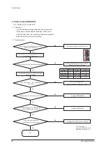
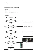
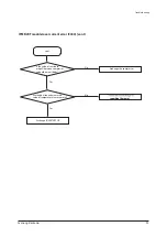
Page 76: ...ng normally low voltage or open Outdoor unit capacity 9kW When the water flow rate is less than 0 7V or greater than 4 5V Outdoor unit capacity 9kW When the water flow rate is less than 0 9V or greater than 4 5V Check water pump operates properly Does flow Sensor connector come out of the PBA Yes After putting out the connector F S from the PBA Measure its status is low voltage or open Re start af...

Page 77: ...29 7 2 00 30 7 2 05 31 7 2 10 32 7 2 15 33 7 2 20 34 6 2 25 35 6 2 30 36 6 2 35 37 6 2 40 38 6 2 45 39 6 2 50 40 6 2 55 41 5 2 60 42 5 2 65 43 5 DC Voltage Water flow rate 2 70 44 5 2 75 45 5 2 80 46 5 2 85 47 4 2 90 48 4 2 95 49 4 3 00 50 4 3 05 51 4 3 10 52 4 3 15 53 4 3 20 54 3 3 25 55 3 3 30 56 3 3 35 57 3 3 40 58 3 3 45 59 3 3 50 60 3 3 55 61 2 3 60 62 2 3 65 63 2 3 70 64 2 3 75 65 2 3 80 66 ...

Page 78: ...ut the connetor in the PBA Yes 1 How to check Water pump is detected only during stop Flow Sensor needs to be replaced If water pump is off Yes No After putting out the connector F S from the PBA Measure its status is low voltage or open Does flow Sensor connector come out of the PBA Yes After putting out the connector F S from the PBA Measure its status is low voltage or open No Is it short Yes N...

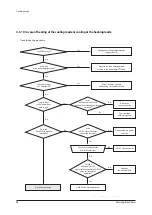
Page 79: ...eplacing the PCB Restart the system after connecting to the PCB connector Temperature sensor failure replace Remove the temperature sensor connector from the PCB and measure the resistance between two terminals 4 3 4 Hydro unit temperature sensor open short Current temperature C Resistance kΩ 60 59 16 55 69 44 50 81 92 45 96 95 40 115 4 35 137 8 30 165 7 25 200 20 242 5 15 295 4 10 362 4 204 Type ...

Page 80: ...tage waveform between the lines square wave with amplitude over 0 7V as shown in the following picture 0 7V 0 7V Good Bad Check the communication cable and replace the Hydro unit unit PCB Remove the communication cable connecting the outdoor unit to Hydro unit unit and measure the signal on LINE 2 of the outdoor unit with a scope Reconnect the cable connecting the outdoor unit to the Hydro unit un...

Page 81: ...digit 1s digit C 8 Outlet water sensor MONO 8 10s digit 1s digit C 9 Cond sensor 9 10s digit 1s digit C 10 Current A 10s digit 1s digit First decimal A 11 Fan RPM B 1000s digit 100s digit 10s digit rpm 12 Target discharge temperature C 100s digit 10s digit 1s digit C 13 EEV D 1000s digit 100s digit 10s digit step 14 Protective control E 0 Cooling 1 Heating Protective control 0 No protective contro...

Page 82: ...Bad Check the communication cable and exchange the Hydro Unit PCB Remove the communication cable connecting the outdoor unit to indoor unit and measure the signal on LINE 2 of the outdoor unit with a scope Reconnect the cable connecting the outdoor unit to the indoor unit and restart the unit If the communication still doesn t work replace the comm kit PCB and Check the communication cable in each...

Page 83: ...rly between MAIN PBA and INVERTER PBA 2 Is the power cable connected correctly 2 Check procedure Does the communication error occur Yes No Normal operation Is the communication power cable connected properly between MAIN PBA and INVERTER PBA Yes Connect the connector right position Exchange MAIN PBA INVERTER PBA in order of mention No CN305 in MAIN PBA CN31 in INVERTER PBA ...

Page 84: ...re condition Check the sensor cable and connector Does the value of resistance satisfy the each temperature condition Yes No Exchange the temperature sensor Power on Yes Is the wire of sensor broken or is there any poor contact Yes No the temperature sensor CN43 in MAIN PBA Pin no Temp sensor Error code 1 2 Outdoor E221 3 4 Condenser E231 5 6 Discharge E251 7 8 OLP E320 Error code for each tempera...

Page 85: ... each resistance of FAN cable housing normal Resistance of FAN cable housing at the normal temperature 10 C 30 C wire pin number Resistance Remark RED BLACK 1 3 over 1MΩ 300V motor power WHITE BLACK 4 3 1KΩ 2KΩ 15V control power YELLOW BLACK 5 3 200KΩ 300KΩ control BLUE BLACK 6 3 10KΩ 50KΩ pulse ORANGE BLACK 7 3 10KΩ 50KΩ reverse Mount each Fan housing to PCB socket and turn on the power Follow th...

Page 86: ...ont Yes Yes No No Cont Exchange INVERTER PCB Exchange the FAN motor Is the Pin voltage 6 3 of CN90 and 91 changed high 4 5V and low 0 1V in case of making manual rotation slowly Is the Pin voltage 7 3 of CN90 and 91 low 0 1V in normal rotation Exchange INVERTER PCB ...

Page 87: ...n Is the value of resistance between each phase for compressor smaller than 2Ω Yes No 3 Is the resistance normal between each phase for compressor Exchange the compressor Is the value of resistance megaΩ between compressor and outdoor unit body Yes No Yes No Check the wire of compressor Compressor starting error E461 Compressor wire missing error E467 U V V W W U Exchange the compressor Is the wir...

Page 88: ...remove the obstacle Yes No 3 Does the fan of outdoor unit work normally Does the compressor work normal Yes No Are the service valves fully opened Yes No Open the service valves Primary current trip error E462 Over current trip PFC over current error E463 Exchange the compressor 4 Is there any obstacle around indoor and outdoor unit Is the indoor unit installed well according to installation manua...

Page 89: ...cle Yes No 3 Is the connection of compressor correctly Are the service valves fully opened Yes No Open the service valves 4 Is there any obstacle around indoor and outdoor unit Is the indoor unit installed well according to installation manual Reinstall after remove the obstacle Is the wire of compressor connected correctly Yes No Check the wire of compressor Is the value of resistance between eac...

Page 90: ...r e v o e l u d o m T B G I M P I Yes No Are the position and measured value of temperature sensor normal reposition the sensor reposition the sensor cont Is the value of resistance megaΩ between compressor and outdoor unit body Yes No Exchange the compressor Exchange INVERTER PCB ...

Page 91: ... power connected correctly 2 Check procedure Is the power cable connected correctly Yes No Connect the power cable Yes No Check whether a fuse has blown Yes No Exchange the fuse Is the reactor connected correctly Check the connection of reactor Does the error occur frequently Yes No Exchange INVERTER PCB Check the input power AC 230V 15 ...

Page 92: ...e error occur Yes No Normal operation Yes No Are the service valves fully opened Yes No Open the service valves Is the evaporator sensor of indoor unit connected correctly Yes No Connect the sensor s connector Yes No Charge refrigerant Is the value of resistance between each phase for compressor smaller than 2Ω Exchange the compressor U V V W W U Is refrigerant charged Exchange INVERTER PCB ...

Page 93: ...e coil Go to the next page 4 WAY valve main body error Attach the sensor correctly Over shortage of the refrigerant Connect the connecter correctly 4 WAY valve coil error Exchange the outdoor PCB No Yes Yes Yes OK Yes No No No NG No Is much frost in the indoor heat exchanger Does the 4 WAY valve operate normally Is the outdoor air sensor and outdoor heat exchanger attached correctly Is the 4 WAY v...

Page 94: ...ge of DC300V apply to the connector of outdoor fan during the operation of outdoor unit The over shortage of refrigerant t Capacity Load estimation error Connect the connector Outdoor fan error Check the motor wire Exchange the out PCB EEV coil error Connect the connector Is much frost in the heat exchanger Is much frost in the heat exchanger Outdoor PCB error EEV main body error No No NG No Yes N...

Page 95: ...outdoor unit power supply N R N S N T 220Vac Yes Check connection of the outdoor unit terminal block No Is the outdoor unit power voltage L N 220Vac Yes Check the connection wires and connectors of the indoor and outdoor units No Is the indoor unit power supply voltage L N 220Vac Yes Exchange the wired remote controller No Does the air conditioner operate when pressing ON OFF button of the wired r...

Page 96: ...9 MAIN PCB CN31 INVERTER PCB Is the FUSE on INVERTER PCB blown Check and correct the wire or socket connection Check Fuses listed blow 3 FUSES in EMI PCB 1 FUSE in MAIN PCB No Is there miss connection of power and communication wire between indoor and outdoor Correct the cable wiring between indoor and outdoor Check F1 F2 communication line wiring CN50 MAIN PCB Check and correct the wiring Exchang...

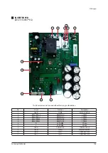
Page 97: ...msung Electronics 5 PCB Diagram 5 1 Tank Integrated Hydro Unit This Document can not be used without Samsung s authorization 22 23 24 25 26 28 27 9 11 10 13 15 14 12 16 19 20 17 18 1 2 3 7 8 4 6 5 21 29 30 31 ...

Page 98: ...R SENSOR SMW250 02 BLK 14 CN5045 MIXING VALVE SENSOR SMW250 02 BLU 15 CNS044 ROOM SENSOR SMW250 02 WHT 16 CNS202 F1 F2 GND DC12V SMW200 04 WHT 17 CNS012 DC12V YW396 02V BLU 18 CNS042 WATER TANK SENSOR SMW250 02 YEL 19 CNS304 F3 F4 YW396 02V RED 20 CNS063 EEV SMW250 06 BLU 21 CNS057 FLOW SENSOR SMW250 04 WHT 22 CNS046 PV SIGNAL SMART GRID BR 7623C 2P BLK 23 CNS808 DC FAN SMW250 03 YEL 24 CNS081 ERR...

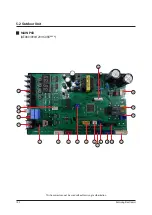
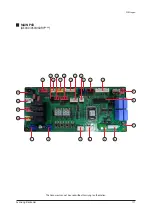
Page 99: ...102 Samsung Electronics 5 2 Outdoor Unit MAIN PCB AE080 090 120 160RX This Document can not be used without Samsung s authorization 1 5 6 8 4 2 3 9 11 10 7 12 13 14 15 16 18 19 20 17 ...

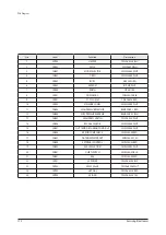
Page 100: ...N803 EEV1 SMW250 05 BLU 8 CN407 HIGH PRESSURE SWITCH SMW250 02 BLU 9 CN802 EEV4 SMW250 06 BLU 10 CN306 DOWNLOAD YDW200 20 BLK 11 CN403 OUT TEMP COND DISCHARGE OLP SMW250 10 WHT 12 CN703 BASE HEATER YW396 03AV BLU 13 CN702 4WAY 1 YW396 03AV YEL 14 CN101 POWER YW396 03AV WHT 15 CN806 EEPROM B7P MQ WHT 16 CN304 DRED DAPC 2009 6P BLK 17 CN501 MODE SELECTOR SMW250 03 WHT 18 CN103 EARTH YDW236 01 WHT 19...

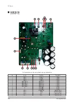
Page 101: ...MP U YTR250 2 CN402 COMP V YTR250 3 CN403 COMP W YTR250 4 REACTOR_A2 REACTOR_A YTR250 5 REACTOR_A1 REACTOR_A YTR250 6 REACTOR_B2 REACTOR_B YTR250 7 REACTOR_B1 REACTOR_B YTR250 8 N AC POWER OT 048 9 L AC POWER OT 048 10 CN551 DOWNLOAD YDW200 20 BLK 11 CN351 COMM SMW250 06 WHT 12 CN901 FAN 1 YW396 06V WHT 13 CN911 FAN 2 YW396 06V WHT 1 13 12 2 3 11 10 9 8 7 5 6 4 ...

Page 102: ...on Description 1 CN401 COMP 42819 3213 BLK 2 REACTOR_A2 REACTOR_A YTR250 3 REACTOR_A1 REACTOR_A YTR250 4 REACTOR_B2 REACTOR_B YTR250 5 REACTOR_B1 REACTOR_B YTR250 6 N AC POWER OT 048 7 L AC POWER OT 048 8 CN551 DOWNLOAD YDW200 20 BLK 9 CN351 COMM SMW250 06 WHT 10 CN901 FAN 1 YW396 06V WHT 11 CN911 FAN 2 YW396 06V WHT 7 6 5 3 4 2 8 9 10 11 1 ...

Page 103: ...ion Description 1 CN400 COMP 42819 3213 BLK 2 CN101 REACTOR HLW1005 02 BLK 3 R AC POWER YTR250 4 S AC POWER YTR250 5 T AC POWER YTR250 6 CN150 AC POWER YW396 03AV WHT 7 CN151 HIGH PRESSURE SWITCH YW396 02V WHT 8 CN551 DOWNLOAD YDW200 20 BLK 9 CN901 FAN 2 YW396 06V WHT 10 CN900 FAN 1 YW396 06V WHT 11 CN351 COMM SMW250 06 WHT 1 11 10 9 8 7 6 5 4 3 2 ...

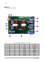
Page 104: ...n not be used without Samsung s authorization EMI PCB AE090 120 160RX EG No Local Function Description 1 L1 AC POWER OT 048 2 CN8 EARTH YTR250 3 CN4 AC POWER L OT 048 4 CN5 AC POWER N OT 048 5 N1 AC POWER OT 048 6 CN01 AC POWER YW396 03AV WHT 1 3 2 4 5 6 ...

Page 105: ... s authorization No Local Function Description 1 CN01 AC POWER YW396 03AV WHT 2 EARTH EARTH YEL GRN WIRE 3 R IN AC POWER WHT WIRE 4 S IN AC POWER BRN WIRE 5 T IN AC POWER BLK WIRE 6 N IN AC POWER SKY BLU WIRE 7 N INV AC POWER SKY BLU WIRE 8 T INV AC POWER BRN WIRE 9 T OUT AC POWER YTR250 10 S OUT AC POWER YTR250 11 R OUT AC POWER YTR250 ...

Page 106: ... Samsung Electronics 109 SUB HEATER PCB AE080 090 120 160RX No Local Function Description 1 CN02 POWER YW396 03AV YEL 2 CN03 HEATER YW396 03AV WHT 2 1 This Document can not be used without Samsung s authorization ...

Page 107: ...W200 20 BLK 3 CN401 COMP U YTR250 4 CN402 COMP V YTR250 5 CN403 COMP W YTR250 6 CN051 REACTOR YTR250 7 CN052 REACTOR YTR250 8 CN002 AC POWER L YTR250 9 CN003 EARTH GP881205 10 CN001 AC POWER N YTR250 11 CN241 HOT GAS YW396 03AV YEL 12 CN030 4WAY AC POWER YW396 03AV WHT 13 CNP351 MAIN COMM SMW250 08 WHT 14 CN571 ECO DOWNLOAD SMW250 04 WHT 15 CNP901 BLDC FAN YAW396 06V WHT 1 7 6 5 4 3 2 8 9 10 11 12...

Page 108: ...PCB Diagram Samsung Electronics 111 MAIN PCB AE040 050 060RX This Document can not be used without Samsung s authorization 22 23 24 25 1 2 3 4 5 6 7 9 8 10 11 12 15 17 19 21 13 14 16 18 20 ...

Page 109: ...05 HIGH PRESSURE SENSOR B04B XARK 1 RED 12 CN404 LOW PRESSURE SENSOR B04B XAEK 1 BLU 13 CN003 HIGH PRESS SWITCH YW396 02V WHT 14 CN806 R32 GAS SENSOR SMW250 04 WHT 15 CN401 OUT TEMP DISCHARGE COND OLP SMW200 08 WHT 16 CN805 ERROR COMP CHECK SMW250 04 RED 17 CN402 WATER IN WATER OUT SMW250 04 YEL 18 CN804 EXTERNAL CONTROL SMW250 02 RED 19 CN403 EVA IN SUCTION SMW250 02 WHT 20 CN001 QUIET SWITCH SMW...

Page 110: ...Samsung Electronics 113 6 Wiring Diagram 6 1 Hydro unit 6 1 1 3Phase Model This Document can not be used without Samsung s authorization ...

Page 111: ...Wiring Diagram 114 Samsung Electronics This Document can not be used without Samsung s authorization 6 1 2 1Phase Model ...

Page 112: ...Samsung Electronics 115 6 2 Outdoor Unit 3Phase AE080 090 120 160 RX GG This Document can not be used without Samsung s authorization ...

Page 113: ...Wiring Diagram 116 Samsung Electronics 1Phase AE090 120 160 RX EG This Document can not be used without Samsung s authorization ...

Page 114: ...Wiring Diagram Samsung Electronics 117 1Phase AE040 050 060RX This Document can not be used without Samsung s authorization ...

Page 115: ...00 200 Liter 50 WATT 100 260 Liter 60 WATT 100 80 WATT 100 90 WATT 100 120 WATT 100 140 WATT 100 160 WATT 100 Mode G Heat Pump R 32 Feature 1 Y Indoor Unit HYDRO UNIT Wall mounted W Indoor Unit Tank Integrated Hydro Unit E Outdoor Unit Split Y Outdoor Unit Mono Power E E 220 240V 50Hz 1Ø G G 380 415V 50Hz 3Ф N R S E G W Series version Feature 1 Y E Series version Feature 1 W D STANDATRD STANDARD T...

Page 116: ...r T_eva in Eva In temp sensor T_eva out Eva Out temp sensor T_tank Water tank temp sensor T_D Discharge temp sensor PS_H High pressure switch V_4W 4Way valve PT_C Charging port HX_M Outdoor Heat exchanger OFM Outdoorfanmotor T_CO Condouttempsensor HX_PHE Plateheatexchanger E_M Mainexpansionvalve 7 2 Tank intergrated hydro unit SPLIT ...

Page 117: ... T_WO WaterPHXOutlettempsensor T_w3 WaterOutlettempsensor T_II EvaIntempsensor T_tank Watertanktempsensor T_D Dischargetempsensor PS_H Highpressureswitch V_4W 4Wayvalve PT_C Chargingport HX_M OutdoorHeatexchanger OFM Outdoorfanmotor T_CO Condouttempsensor HX_PHE Plateheatexchanger E_M Mainexpansionvalve ...

Page 118: ...ung Electronics 121 7 4 FSV Data check and update using S NET Pro2 To check the EHS FSV data the Update button must be selected FSV value has been updated double click each cell can set the value of the FSV ...

Page 119: ...122 Samsung Electronics 7 5 EHS FSV Values Import and Export The User can now export the existing FSV values into an XML file and update later onto a new unit the saved values ...

Page 120: ...he existing FSV values can be exported by click on the Export button FSV Import The FSV values can be imported by the click on the import button The user is prompted to browse and select the XML file for update on the EHS unit selected in the dropdown menu ...

Page 121: ...Reference Sheet 124 Samsung Electronics SD Card The FSV values can be loaded from SD card or saved to SD card by the click on the import button SD card should be connected in EHS Converter ...

Page 122: ...cable International and or domestic law Samsung Electronics Co Ltd April 2019 Printed in Korea Code No AC 00242E_1 GSPN Global Service Partner Network Area Web Site Eurpoe CIS Mideast Africa gspn1 samsungcsportal com Asia gspn2 samsungcsportal com North Latin America gspn3 samsungcsportal com China china samsungportal com ...

Reviews: