background image

4-25

4. Troubleshooting 

DDC Input Process

Connecting D-sub cable between the parallel port(printer port) of computer and Monitor


PC

Connecting to the parallel port of computer

Connecting to Monitor


1

2

3

4

The DDC input is available after entering the Service Mode. : Cancel the DDC Protection.

1: Open the file.
2: Select Port 1 (D-SUB) / Select Port 2(DVI) / Select Port 3(HDMI)
3: Select the DDC file.
4: Click the Next(OK) button.

Summary of Contents for 820DXn - SyncMaster - 82" LCD Flat Panel Display

Page 1: ... LCD Monitor Contens 820DXn Refer to the service manual in the GSPN see the rear cover for the more information 1 Precautions 2 Product specifications 3 Disassembly and Reassemble 4 Troubleshooting 5 Exploded View Part List 6 Wiring Diagram 7 Schematic Diagram ...

Page 2: ... PC D SUB Video 4 4 4 4 No DVI Video 4 6 4 5 No BNC Video 4 8 4 6 No Component Video Component 4 10 4 7 No AV Video AV 4 12 4 8 O S Problems 4 14 4 9 Faults and Corrective Actions 4 16 4 6 Adjustment 4 17 5 Exploded View Part List 5 1 5 1 Exploded View 5 1 5 2 Parts List 5 3 6 Wiring Diagram 6 1 6 1 Wiring Diagram Main 6 1 6 2 Wiring Diagram Network 6 2 6 3 Wiring Diagram Main Power 6 3 6 6 Wiring...

Page 3: ...urope samsungportal com China http china samsungportal com Asia http asia samsungportal com Mideast Africa http mea samsungportal com This Service Manual is a property of Samsung Electronics Co Ltd Any unauthorized use of Manual can be punished under applicable International and or domestic law 2008 Samsung Electronics Co Ltd All rights reserved Printed in Korea P N BN82 00428A 00 ...

Page 4: ...rce before disassembly 2 Follow these directions carefully never use metal instruments to pry apart the cabinet 3 When disassembling the monitor do not use any metal tools except for the provided jig Description Picture Description Screws 1 Remove 17 screws from the rear cover and lift up the rear cover 2 Remove the twenty 20 screws on the shield cover and remove it 3 Remove the four 2 screws and ...

Page 5: ...ion Screws 5 Remove the screws and the board designated in the right photo and then place the set down 6 Remove the four 15 screws shown in the figure and remove the board 7 Remove the 4 screws designated in the right photo and remove the speaker 8 Down the panel ...

Page 6: ... Picture Description Screws 9 Remove the screws designated in the right photo and remove the stand 10 Remove the screws designated in the right photo and remove the bracket Reassembly procedures are in the reverse order of disassembly procedures ...

Page 7: ...3 4 3 Disassembly and Reassemble Memo ...

Page 8: ...5 1 5 Exploded View Part List 5 Exploded View Part List 5 1 LS82BPTNBF XSF Exploded View 820DXN F001A M0215 BN91 01855A M0412 T0152 M0002 M0003 BN61 03645A M0013 ...

Page 9: ...2BPT PIVOT 1 SNA M0003 BN96 06315A ASSY STAND P Beethoven Plus 82 AL T3 2 SA M0013 BN96 06313B ASSY COVER P REAR LS82BP SECC PIVOT T1 0 1 SA M0215 BN07 00416A LCD PANEL LTI820HT L01 SSZZT1 8bit 82 0i 1 SA M0412 BN96 06314B ASSY BRACKET P PCB Beethoven Plus 82 SEC 1 SNA T0152 BN96 06364A ASSY BRACKET P VESA BEETHOVEN 70 82 SE 4 SNA BN91 01855A ASSY SHIELD LS82BPTNB XAA 1 SNA BN61 03645A BRACKET SUP...

Page 10: ...LABEL WINDOWS XP BE40 coated white pol 1 SNA 2 M0013 BN96 06313B ASSY COVER P REAR LS82BP SECC PIVOT T1 0 1 SA 3 M0006 BN63 04061B COVER REAR LS82BP SECC T1 0 BLACK PIVOT 1 SNA 2 M0081 6003 000337 SCREW TAPTYPE BH S M4 L10 ZPC BLK SWR 36 SA 2 M0006 BN63 04058A COVER REAR SUB BEETHOVEN_PLUS 82 SECC T 1 SNA 0 1 M0019 BN91 01682E ASSY LCD SPZ LS82BPT 1 SNA 2 M0215 BN07 00416A LCD PANEL LTI820HT L01 S...

Page 11: ...PEM PND M8 D14 L16 ZPC SIL SUM24L 4 SNA 4 M0113 BN61 03627A BRACKET VESA BEETHOVEN_PLUS 82 SECC 2 0 4 SNA 2 M0523 BN96 06365B ASSY BRACKET P WALL BEETHOVEN 82 AL Ex 2 SNA 3 M0081 6003 000337 SCREW TAPTYPE BH S M4 L10 ZPC BLK SWR 48 SA 3 T0101 BN61 03621B BRACKET WALL BEETHOVEN_PLUS 82 SECC 2 0 2 SNA 3 T0101 BN61 03628A BRACKET WALL TOP BEETHOVEN_PLUS 82 AL 2 2 SNA 3 T0101 BN61 03628B BRACKET WALL ...

Page 12: ...2 M2893 BN39 00845A LEAD CONNECTOR LS57BP UL1007 26 3P 700 mm 1 SA 2 T0382 BP61 00495C HOLDER CARE PJT ACRYL FOAM T0 25 W30 0mm 0 1 SNA 2 M2893 BN39 00979B LEAD CONNECTOR BeethovenPlus 82 UL2464 2 1 SNA 2 0201 001563 ADHESIVE HM 3748 YEL 8500CPS 0 003 SNA 2 T0243 BN31 00026C FAN ASSY G6015S12B2 AG OC EM 2BALL LFD 4 2 SA 3 T0081 AA60 10050T SCREW TAPPING RH 2S M4 L20 ZPC BLK SW 4 SNA 3 T0136 BN31 0...

Page 13: ...SNA 2 BN69 03776B BOX 02 SET OUT LS82BPT CB C 03 DY 06 AB 2 SNA 0 1 T0909 BN94 01370T ASSY PCB MISC NETWORK DP LS82BPTNB XSF 1 SNA 2 BN98 00807A ASSY K D PACKING NETWORK BEETHOVENPLUS 1 SNA 3 T0214 0203 001269 TAPE OPP MASKING 301 T0 06 W75 L50000 N 0 16 SNA 3 6902 000015 BAG ANTISTATIC LDPE T0 05 W900 L950 TRP 1 SNA 3 6902 000604 BAG WRAPPING LDPE T0 02 W500 L10000 TRP 0 34 SNA 3 M040 6922 000013...

Page 14: ...h 2 SA 4 L0405 0601 001313 LED SMD GRN 2X1 8MM 565NM 3 16X1 6X1 1MM 1 SA 4 L0405 0601 001419 LED SMD RED 3 2X1 6X1 1MM 660NM 3 2X1 6X 1 SA 4 0904 002201 IC I O CONTROLLER IT8718F PQFP 128P 20x1 1 SNA 4 0904 002281 IC GRAPHIC CONT 216TQA6AVA12FG FCBGA 46 1 SA 4 0904 002282 IC SYSTEM PERI 218S6ECLA21FG FCBGA 549P 1 SA 4 1001 001330 IC ANALOG SWITCH FSA4157P6X_ NL MAA06A 6P 2 SA 4 1003 002059 IC POWE...

Page 15: ...2007 000669 R CHIP 2Kohm 1 1 10W TP 1608 3 SNA 4 R346 2007 000729 R CHIP 300ohm 5 1 10W TP 1608 15 SNA 4 R2007 2007 000803 R CHIP 36Kohm 1 1 10W TP 1608 2 SA 4 RF03 2007 000828 R CHIP 39Kohm 1 1 10W TP 1608 2 SA 4 AR61 2007 000869 R CHIP 4 7Kohm 1 1 10W TP 1608 1 SNA 4 HR10 2007 000962 R CHIP 5 1Kohm 1 1 10W TP 1608 1 SA 4 PR12 2007 000979 R CHIP 5 6Kohm 1 1 10W TP 1608 1 SA 4 AAR20 2007 001002 R ...

Page 16: ...5249 C CER CHIP 100nF 10 50V X7R TP 1608 3 SNA 4 C410 2203 005384 C CER CHIP 4700nF 80 20 10V Y5V TP 201 2 SNA 4 AD480 2203 005437 C CER CHIP 10000nF 80 20 10V Y5V 3216 3 SNA 4 AD480 2203 005533 C CER CHIP 1000nF 20 6 3V X7R TP 1608 14 SNA 4 EC9 2203 005834 C CER CHIP 22000nF 80 20 10V Y5V 3216 31 SA 4 C236 2203 005918 C CER CHIP 1000nF 10 6 3V X7R 1608 8 SNA 4 VC37 2203 006048 C CER CHIP 100nF 10...

Page 17: ...ILICON AOD4184A N 40V 50A 0 007ohm 12 SA 3 0902 002380 IC MICROPROCESSOR ADH4450IAA5DO 2 30G Hz 1 SA 3 3709 001371 CONNECTOR CARD EDGE 240 2 1 9mm STRAIGHT 2 SNA 3 M0018 BN97 01831A ASSY MICOM NETWORK M_ FIDXPE04FHD_1008 0 1 SA 4 1109 001388 IC ETC MEMORY DM254G20H200 4GByte 4Gbit 1 SNA 3 BN96 05731B ASSY HEAT SINK P LH40BVT BN61 03489A BN6 1 SNA 3 1105 002033 IC DRAM MODULE M378T2863EHS CF7 DDR2 ...

Page 18: ...09 0505 001170 FET SILICON FDS9933A P 20V 3 8A 0 075oh 2 SA 4 Q409 0505 002169 FET SILICON Si4435BDY T1 E3 P 30V 9 1A 1 SA 4 IC104 0801 002171 IC CMOS LOGIC 74LCX125 BUS BUFFER SOP 14 1 SA 4 M0215 0801 002198 IC CMOS LOGIC 74LVC14 INVERTER SOP 14P 1 2 SA 4 IC105 0909 001032 IC REAL TIME CLOCK PCF8563 SOP 8P 4 9x3 1 SA 4 IC110 1006 001076 IC DRIVER RECEIVER MAX232ECWE T SOP 16P 1 SA 4 IC112 1103 00...

Page 19: ...7 SNA 4 MR112 2007 000309 R CHIP 10ohm 5 1 10W TP 1608 5 SA 4 ER13 2007 000669 R CHIP 2Kohm 1 1 10W TP 1608 1 SNA 4 R346 2007 000729 R CHIP 300ohm 5 1 10W TP 1608 12 SNA 4 HR13 2007 000821 R CHIP 390ohm 1 1 10W TP 1608 2 SNA 4 AR61 2007 000869 R CHIP 4 7Kohm 1 1 10W TP 1608 7 SNA 4 R419 2007 000882 R CHIP 4 7ohm 5 1 10W TP 1608 8 SA 4 HR10 2007 000962 R CHIP 5 1Kohm 1 1 10W TP 1608 2 SA 4 AR39 200...

Page 20: ...0 2012 3 SA 4 VL6 2703 000398 INDUCTOR SMD 10uH 10 3225 3 SA 4 T0052 2703 001334 INDUCTOR SMD 1 5uH 10 2012 1 SA 4 T0052 2703 001778 INDUCTOR SMD 3 3uH 20 3225 2 SA 4 T0052 2703 002937 INDUCTOR SMD 33uH 20 12x12mm 2 SNA 4 T0052 2704 000018 INDUCTOR SMD ARRAY 15uH 2000mA 2 0 124oh 2 SA 4 X202 2801 000258 CRYSTAL SMD 0 032768MHz 20ppm SMD 12 5pF 1 SA 4 X202 2801 003667 CRYSTAL SMD 14 31818MHz 30ppm ...

Page 21: ...WR 4 SA 3 T0289 BN63 03464A SHIELD JACK BEETHOVEN PLUS 40 SECC T0 8 1 SNA 3 M0131 BN63 04464A GASKET BeethovenPlus 57 Conductive Fabri 1 SNA 3 6011 001445 BOLT SOCKET 4 40 UNC L7 NI PLT BRASS HEX 8 SNA 2 BN98 00808C ASSY K D PACKING MAIN BEETHOVENPLUS BN4 1 SNA 3 T0214 0203 001269 TAPE OPP MASKING 301 T0 06 W75 L50000 N 0 17 SNA 3 6902 000314 BAG AIR CAP LDPE T0 05 W400 L400 TRP 6 6 1 SNA 3 6902 0...

Page 22: ...onal Standards Institute ANSI C101 1 Leakage Current for Appliances and Underwriters Laboratories UL Publication UL1410 59 7 With the unit completely reassembled plug the AC line cord directly into a 120V AC outlet With the unit s AC switch first in the ON position and then OFF measure the current between a known earth ground metal water pipe conduit etc and all exposed metal parts including metal...

Page 23: ...trument s ground lead last 1 3 Static Electricity Precautions Some semiconductor solid state devices can be easily damaged by static electricity Such components are commonly called Electrostatically Sensitive Devices ESD Examples of typical ESD are integrated circuits and some field effect transistors The following techniques will reduce the incidence of component damage caused by static electrici...

Page 24: ...om being exposed to moisture Otherwise it may cause a fire or electric shock Make sure to turn the power off and unplug the power cord from the outlet before repositioning the product Also check the antenna cable or the external connectors if they are fully unplugged Damage to the cord may cause fire or electric shock Keep the antenna far away from any high voltage cables and install it firmly Con...

Page 25: ...1 4 1 Precautions Memo ...

Page 26: ...SA Wall Mount Kit Specifications Item Description Model SyncMaster 820DXn LCD Panel AMLCD 82 LTI820HT L01 Optimal Resolution 1920 Horizontal x 1080 Vertical WXGA 60Hz Maximum Resolution 1920 Horizontal x 1080 Vertical WXGA 60Hz Input video signa 0 7Vp p 5 at a terminal resistance of 75Ω bipolar signal Input Sync Signal Type Separated horizontal and vertical synchronizations on green signals Auto s...

Page 27: ...on Model SyncMaster 820DXn Environmental Considerations Operating Temperature 10 C 50 C 50 F 122 F Operating Humidity 10 90 Operating Temperature 20 C 45 C 4 F 113 F Operating Humidity 5 90 Designs and specifications are subject to change without prior notice ...

Page 28: ...8 8ms 450cd m2 1200 1 178 178 8ms Input PC D Sub DVI D BNC D Sub DVI D BNC Video S Video CVBS Component HDMI S Video CVBS Component Feature Speaker 15 Watts x 2 ch SRS Trusrround 10 Watts x 2 ch SRS Trusrround Finction Power On Delay Network Option Safety Screen Monitor information S N Video Wall MDC Program Power On Delay Network Option Safety Screen Monitor information S N Video Wall MDC Program...

Page 29: ...00992A Samsung Electronics Service center Warranty Card Not available in all locations BH68 00261F Natural Color MDC MagicNet Software User s Manual BN59 00654A D Sub 15 Pin Cable BN39 00244B Power Cord 3903 00280 BNC to RCA Adaptor Jack 3705 001262 Remote Control BN59 00489A Batteries AAA 2 4301 000121 ...

Page 30: ...t specifications 2 4 Accessories Sold separately Product Description Ccde No Remark DVI Cable BN39 00246F Samsung Electronics Service center Wall Mount KIT WNN 7070 VESA bracket BN96 01791A RS232C cable BN39 00341A ...

Page 31: ...2 6 2 Product specifications Memo ...

Page 32: ...If no picture appears make sure the power cord is correctly connected Check the following circuits No raster appears Function PBA Main PBA I P PBA 5V develop but no screen Main PBA 5V does not develop I P PBA After soft power turn off push the mute 1 8 2 power on and so enter the Service Menu If you choose the reset the monitor automatically returns to factory reset 1 2 3 4 ...

Page 33: ...er there is any abnormal output at other output terminals Diagnostics C653 C603 C622 CN602 BD643 Main Board Front Yes Check the SMPS Board No Does 5 2 V appear at Pin 15 of CN602 Does DC 12V appear at BD643 Check the LCD Panel No Yes Check the peripheral circuit of CN602 No Does DC 12V appear at C653 Yes Replace IC602 No Does 3 3V appear at C622 Yes Replace IC601 No Does DC 1 8V appear at C603 Yes...

Page 34: ...4 3 4 Troubleshooting 4 2 1 Waveform ...

Page 35: ...s CN403 C603 CN101 IC103 Main Board Front YES Check the power port No Does the LED light up when turn on the power Does 5V appear at Pin 9 of CN101 D Sub Check the cable connection No YES Does the waveform as the figure at Pin 6 H sync and Pin 8 V sync of IC103 appear Replace IC103 No YES Is TX signal sent to Pin 14 and 15 of CN403 14 15 The Scaler IC408 is abnormal Replace the main board No YES C...

Page 36: ...4 5 4 Troubleshooting 4 3 1 Waveform ...

Page 37: ...n Board Front Yes Check the power port No Does the LED light up when turn on the power Does 5 V appear at Pin 14 and 16 of CN101 DVI port Check the cable connection No Yes Does the wave form as the figure appear at R116 DVI_SCL and R120 DVI_SDA Replace the main board No Yes Does the signal appear at RA105 R RA101 G and RA103 B IC105 is abnormal Replace the main board No Yes Does the TX signal appe...

Page 38: ...4 7 4 Troubleshooting 4 4 1 Waveform ...

Page 39: ...cs CN403 IC103 ZD115 113 ID114 Main Board Front Yes Press the power button and check the LED No Does 3 3 V appear at ZD114 118 Is the cable properly connected Reconnect the BNC cable No Yes Does the wave form appear at Pin 6 H sync And Pin 8 V sync of IC103 Replace IC103 No Yes Does the TX signal appear at Pin 14 and 15 of CN403 The scaler IC408 is abnormal Replace the main board No Yes Check the ...

Page 40: ...4 9 4 Troubleshooting 4 5 1 Waveform ...

Page 41: ...nected correctly to the IP board Diagnostics CN403 R178 R180 R182 ZD115 113 ZD114 Main Board Front Yes Press the power button and check the LED No Does 3 3V appear at ZD114 118 Does the waceform appear at R178 Pr R180 Y R1013 Pb Reconnect the component cable No Yes Does the TX signal appear at Pin 14 and 15 of CN403 The scaler IC408 is abnormal Replace the main board No Yes Check the cable between...

Page 42: ...4 11 4 Troubleshooting 4 6 1 Waveform ...

Page 43: ...nnected correctly to the IP board Diagnostics CN403 IC103 ZD115 113 ID114 R180 L104 L105 Main Board Front Yes Check the power port No Does the LED light up when turn on the power Does the waveform at L104 L105 Reconnect the cable No Yes Does the TX signal appear at Pin 14 and 15 of CN403 The scaler IC408 is abnormal Replace the main board No Yes Check the cable between the main board and panel and...

Page 44: ...4 13 4 Troubleshooting 4 7 1 Waveform ...

Page 45: ... the IP board correctly Diagnostics FDM IC12 Yes Check IC12 and whether the LED is turned on No When turning the power on in MagicNet mode does the Samsung logo screen appear Does the blue screen appear as shown in Figure Replace the FDM No Yes Does the error message appear while booting as shown in the figure Replace the FDM No Yes Check the CPU and the DIMM memory and replace the network board C...

Page 46: ...4 15 4 Troubleshooting 4 8 1 Screens to Check 16 ...

Page 47: ...ning Manual for information on inputting the DVI DDC Symptoms When the monitor is turned on only a full white pattern is displayed continually regardless of the signals Causes This fault occurs when only the lamp power is supplied and no video signals are input to the panel due to a fault or incorrect connections of the LVDS cable Corrective Actions Replace or reconnect the LVDS cable correctly so...

Page 48: ...4 17 4 Troubleshooting 4 6 Adjustment 4 6 1 Entering Service Mode with Remote Control Entering Service Mode Power Off MUTE 1 Power On 8 2 INFO FACTORY Using factory Remocon 4 6 2 Service Mode Menu 1 ...

Page 49: ...60Hz Extreme caution needed Component 720p color bar pattern Color control operates normally only in certain modes of certain patterns but in other cases the operation may distort color Extreme caution needed Used for color control But excessive setting may saturate the color Extreme caution needed Register value in the Scaler RED BLUE GREEN Adjust the Gain and Offset On Display factory adjusting ...

Page 50: ...he more natural video is Too high sharpness may cause the vivid noise Noise Coring Control Peaking Coring Display only the sharp large edge without assuming the small edge of the video as a noise and amplifying it Assign the threshold value to improve the sharpness NonLinear Sharpness Control Peaking Resion1 2 Threshold Gain Divide the frequency area and apply the different Gain for each area rath...

Page 51: ...arget region Change only when it is needed HLE Horizontal Large Edge Enhancer HDP Horizontal Detail Processor HCE Horizontal Chroma Enhancer VDP Vertical Detail Processor The MPEG NR menu is used to reduce the Mosquito noise and Gaussian noise The Fleshtone menu is used to display the natural skin color Enhancers Part Back End Part ...

Page 52: ...oubleshooting Display the panel use time and the number of change Time Reset Press the menu button on the front panel for 5 seconds AV size position Adjustment H V size H V Position Panel Info Part AV Size Part ...

Page 53: ...vice Menu to the default setting Need to turn the Power On Off after reset Spread Spectrum Reset Part NTP3000 Part Controls the amplifier output and PWM mode The default DRC threshold value is used The default value cannot be changed Setting the audio delay Set to synchronize video and audio Set the Speaker EQ setting to On which is the optimal setting for the speakers ...

Page 54: ...e screen quality settings to the factory defaults which are the optimal settings They cannot be changed If they need to be changed specialist help is required for the DNIe screen quality FBEx_WhiteBalance Part Controls the DNIe RGB white balance ...

Page 55: ...tting DVI cable impedance matching setting Check Status Fan Speed Setting If Current Temperature value is over Temperature Control value Monitor enter the Protection Mode Backlight off and Function LED change color Green to Orange Current temperature of the inner monitor Control IR output carrier frequency off 32 36 38 40 56kHz Delay value before the Hot Plug Detect reset Control DVI Impedance val...

Page 56: ... computer and Monitor PC Connecting to the parallel port of computer Connecting to Monitor 1 2 3 4 The DDC input is available after entering the Service Mode Cancel the DDC Protection 1 Open the file 2 Select Port 1 D SUB Select Port 2 DVI Select Port 3 HDMI 3 Select the DDC file 4 Click the Next OK button ...

Page 57: ...erial port of the PC and the input serial port of Beethoven Board with the RS232C cable Option in the Factory Menu Check if BaudRate is set to 115200 5 RS 232C a standard of serial communication is used for the communication between a PC and a display Therefore a serial cable should be connected between the serial port on a PC and the serial port on a display Refer to the diagram ...

Page 58: ... the OK button then press Next to complete the installation Attached The program is not affected by Windows OS system When the installation is complete using the Setup exe file the icon appears on your desktop Double click the icon to run the program ...

Page 59: ...4 28 4 Troubleshooting 1 Flash Download in the File Select menu Set as the figure Chip Model Set 2MB_TORINO first 2 After the installation Connection Set as the figure SERIAL1 COM1 115200 ...

Page 60: ...d Config for the auto setting 4 Select the file you want to download on Browse 5 Press 5 to download Turn the power of the board off on when the download success message appears Check the Checksum and date to see if the right code is applied in the Factory mode ...

Page 61: ...4 30 4 Troubleshooting Installing the MDC Multi Display Control Program 1 Run SETUP EXE 2 Click I Agree 3 Click Next 4 Click Install ...

Page 62: ...4 31 4 Troubleshooting 5 The installation proceeds ...

Page 63: ...rvice mode and turn off the Hard power 2 Network Board Press Info and check the version of Network Check the versions of FDM and BIOS and see if they are the same as the version of the server program If the version is different refer to the descriptions above and upgrade the program Upgrade the program and turn the power off on Check if there are DIMM memory and Battery ...

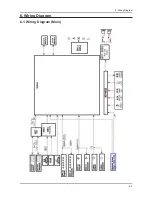
Page 64: ...6 1 6 Wiring Diagram 6 Wiring Diagram 6 1 Wiring Diagram Main ...

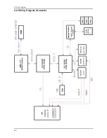
Page 65: ...6 2 6 Wiring Diagram 6 2 Wiring Diagram Network ...

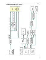
Page 66: ...6 3 6 Wiring Diagram 6 3 Wiring Diagram Main Power ...

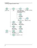
Page 67: ...6 4 6 Wiring Diagram 6 4 Wiring Diagram Network Power ...

Page 68: ...6 5 6 Wiring Diagram PC D SUB DVI Audio BNC Component Audio AV Audio Video S Video Speaker Audio 6 5 Wiring Diagram Photo Main Board ...

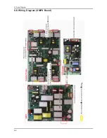
Page 69: ...6 6 6 Wiring Diagram 6 6 Wiring Diagram SMPS Board ...

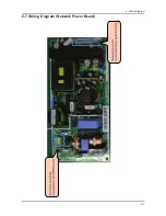
Page 70: ...6 7 6 Wiring Diagram 6 7 Wiring Diagram Network Power Board ...

Page 71: ...6 8 6 Wiring Diagram 6 8 Wiring Diagram ...

Page 72: ...is supplied to the main circuit CN404 Turns the backlight on and controls its brightness and receives the lamp error signals When a problem occurs The LCD backlight is not turned on or becomes darker The LED indicator at the front changes from green to amber and then turns off in amber CN402 Operates when a function key at the front is pressed When a problem occurs The function keys at the front d...

Page 73: ...B BN39 00618D Use The control cable for the main SMPS and the main circuit board The power cable for the SMPS and the circuit board Code Photo BN39 00951A BN39 00984A Use Function Key Cable FAN Cable Code Photo BN39 00936A BN39 00950A Use Panel Inverter Cable Code Photo BN39 00934A ...

Reviews: