background image

Confidential


5G CPE Outdoor Installation Manual   v1.0 


28 

Copyright ©  2018, All Rights Reserved. 

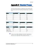
Appendix B 


Standard Torque 

When operator fastens the bolt, use the standard torque values provided in tables 
below to prevent the equipment and bolt from damage and secure by fastening. 
When the torque value for each connection part is defined already, use the defined 
value. 

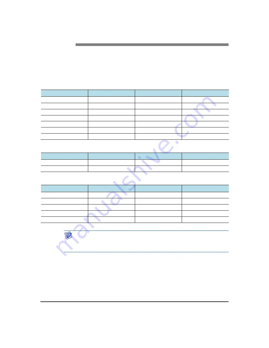
Table 13. Standard Torque Value for Fastening Bolts 

Bolt Spec. 

Torque Value (N·m)


Torque Value (lbf·in)


T

orque Value (kgf·cm)


M3 

0.63 

5.6 

6.4 

M4 

1.5 

13 

15 

M5 

2.8 

25 

29 

M6 

4.9 

43 

50 

M8 

12 

110 

127 

M10 

25 

217 

250 

M12 

42 

372 

428 

Table 14. Brass Bolts Torque Value 

Bolt Spec. 

Torque Value (N·m)


Torque Value (lbf·in)


Torque Value (kgf·cm)


M6 

2.9 

26 

30 

M8 

6.3 

56 

64 

Table 15. Connector Connection Torque Value 

Connector 

Torque Value (N·m)


Torque Value (lbf·in)


Torque Value (kgf·cm)


SMA connector 

0.59 

5.2 

TNC connector 

0.88 

7.8 

N-type connector 

17 

20 

DIN-type connector 

25 

217 

250 

4.3-10-type connector 

44 

51 


Torque value can be different, defending on the material, characteristic, and 
specification of the equipment and fastener. Ensure that you check the proper 
torque value for each specification of the equipment and the fastener. 


Summary of Contents for 5G CPE

Page 1: ...Radio Access Network 5G CPE Outdoor Installation Manual Describes product installation and requirement procedure Document Version 1 0 December 2017 Document Number TBA ...

Page 2: ...n by reason of negligence will be accepted by SAMSUNG Electronics Co Ltd its subsidiaries or employees for any direct or indirect loss or damage caused by omissions from or inaccuracies in this document SAMSUNG Electronics Co Ltd reserves the right to change details in this publication without notice SNMTC v3 0312 This manual should be read and used as a guideline for properly installing and or op...

Page 3: ...iew and External Interface 1 CPE Outdoor View 1 CPE Outdoor External Interface 3 Specifications 4 Cautions for Installation 5 Before Installing 5 While Installing 5 After Installing 5 Installation Tools 7 Chapter 2 Installing System 9 Installation Procedure 9 System Arrangement 10 Transporting and Unpacking 11 Bringing in Items 11 Unpacking Items 11 Fixing System 12 Fixing Unit Bracket Assembly 12...

Page 4: ...igure 7 Fixing Unit Bracket Assembly 1 12 Figure 8 Fixing Unit Bracket Assembly 2 13 Figure 9 Fixing Mounting bracket on the Pole 1 14 Figure 10 Fixing Mounting bracket on the Pole 2 15 Figure 11 Fixing Mounting bracket on the Pole 3 16 Figure 12 Fixing CPE Outdoor on the Pole Mounting Bracket 17 Figure 13 CPE Outdoor Marking Dimensions for Wall Type 18 Figure 14 Marking Wall Type 19 Figure 15 Fix...

Page 5: ... 5 Parts and Tools for Fixing CPE Outdoor on the Pole 16 Table 6 Tools for Marking 17 Table 7 Tools for Drilling 19 Table 8 Anchor Bolt Drill Bits and Hole Depth 19 Table 9 Drilling Example 20 Table 10 Parts and Tools for Fixing Mounting Bracket on the Wall 20 Table 11 Parts and Tools for Fixing CPE Outdoor on the Wall 22 Table 12 Construction Situation Checklist 24 Table 13 Standard Torque Value ...

Page 6: ...vice failure or damage to equipment Provides information or instructions that you should follow to avoid personal injury or fatality Provides antistatic precautions that you should observe Menu Commands menu command This indicates that you must select a command on a menu where menu is the name of the menu and command is the name of the command on that menu File Names and Paths These are indicated ...

Page 7: ...items should be understood before installation Chapter 2 Installing System This chapter describes the procedures to install the CPE Outdoor Chapter 3 Connecting Cables This chapter describes the procedures to connect the cables to the CPE Outdoor installed Chapter 4 Inspect the Installation This chapter describes the procedures of inspecting installation status after CPE Outdoor installation and c...

Page 8: ...ry to personnel or damage to the equipment could result from mistakes Maintenance should only be carried out by trained and competent engineers who are familiar with the relevant procedures and instructions Lasers The product is fitted with optic modules rated as Class 1 radiation emitting devices under EN 60825 1 During installation operation and maintenance never look into the end of an optical ...

Page 9: ...The product is powered from a 48 V DC supply To protect against fire the equipment is fused Environment The product must be operated in an environment with the specified relative humidity and ambient temperature ranges Keep all liquids away from the equipment as accidental spillage can cause severe damage Cooling The product cools down by its own set of cooling fans housed in a fan module Each fan...

Page 10: ...he unit s power supply inlets Other usage will invalidate any approval given to this equipment Connection of this equipment to devices that are not marked with all relevant national safety requirements may produce hazardous conditions on the network When the power supply is obtained by a rectifier safety isolation transformer the supply must meet the requirements of EN 60950 providing double reinf...

Page 11: ...s Hg Cd or Pb indicate that the battery contains mercury cadmium or lead above the reference levels in EC Directive 2006 66 The battery incorporated in this product is not user replaceable For information on its replacement please contact your service provider Do not attempt to remove the battery or dispose it in a fire Do not disassemble crush or puncture the battery End of life recycling materia...

Page 12: ...r and check the terms and conditions of the purchase contract This product and its electronic accessories should not be mixed with other commercial wastes for disposal Correct disposal of batteries in this product Applicable in countries with separate collection systems The marking on the battery manual or packaging indicates that the battery in this product should not be disposed of with other ho...

Page 13: ...items that you should know before installation System View and External Interface This section provides the pictorial view of the CPE Outdoor and its interfaces CPE Outdoor View Figure below depicts the physical structure of the CPE Outdoor Figure 1 CPE Outdoor View Bottom View Top View Left View 10 19 259 2 08 53 Unit in mm Right View Rear View Front View 6 77 172 2 52 64 ...

Page 14: ...tion 5G CPE Outdoor Installation Manual v1 0 2 Copyright 2018 All Rights Reserved Figure 2 CPE Outdoor View include Cable Cover Bottom View Top View Left View 13 71 348 4 2 08 53 Unit in mm Right View Rear View Front View 6 86 174 4 2 52 64 ...

Page 15: ...PE Outdoor Installation Manual v1 0 3 Copyright 2018 All Rights Reserved CPE Outdoor External Interface Figure below depicts the external interface structure of the CPE Outdoor Figure 3 CPE Outdoor External Interface Ground Terminal LAN Bottom View ...

Page 16: ...Port PoE 100Base TX or 1000Base T USB USB 2 0 1 Port Bluetooth BLE4 0 USIM Nano SIM 1 Port Replaceable regular SIM support Class C operating conditions terminal or a smart card operating at 1 8 V 10 LED Total 4EA Power Green LED Signal 3 Color Green Amber Red Connection 3 Color Green Amber Red Alarm 3 Color Green Amber Red Factory Reset 1EA Push Button Switch Operational Temperature Outdoor 30 to ...

Page 17: ...system damage or fatal human injury when connecting or disconnecting cables Ensure that workers wear protection gloves and goggles to prevent injury from debris while drilling holes in a wall or ceiling Do not wear accessories such as watches and rings to prevent electrical shock Cover unused ports with a cap This prevents foreign substances from entering into the unused ports To prevent foreign s...

Page 18: ...anual v1 0 6 Copyright 2018 All Rights Reserved Ensure that the workers do not damage installed cables while cleaning the system While cleaning the power supply device take precaution that the device does not come in contact with foreign objects that may cause power failure ...

Page 19: ...stening M6 SEMS Hexagon 2 Screw Driver Bit Number 2 For fastening M3 Screw Number 3 For fastening M6 SEMS Hexagon 3 Screw Driver Number 2 For loosening M3 Screw Number 3 For loosening M6 SEMS Hexagon T25H For loosening M5 SEMS 4 T25H For fastening Torx Screw T25H 5 Tape Measure 16 ft 150 ft Tape measure for length measurement 6 Power Extension Cable 100 ft Basic tool 7 Level Normal For horizontali...

Page 20: ...ng 16 Knife Basic Tool Cutting 17 Multi tester Digital Pocket Tester To measure voltage and current to detect cable disconnection 18 Compass Normal Check azimuth during installation 19 Heating Gun 50 300 C Shrinking Heat Shrink Tube 20 Hammer Normal Anchor fixing The required installation tools may vary depending on the site conditions In addition to the basic tools protractor ladder safety equipm...

Page 21: ...System This chapter describes installation procedure of the CPE Outdoor Installation Procedure Figure below depicts the procedure to install the CPE Outdoor Figure 4 Procedure to Install the CPE Outdoor Foundation Work Unpacking and Transporting Fixing System Unpacking Items Bringing in Items Pole Type Wall Type ...

Page 22: ...e that must be secured for pole type installation of the CPE Outdoor Figure 5 CPE Outdoor Arrangement Pole type Installation Figure below depicts the minimum distance that must be secured for wall type installation of the CPE Outdoor Figure 6 CPE Outdoor Arrangement Wall type Installation Unit in mm Top View Front View 16 400 8 200 8 200 W 6 86 174 4 H 13 71 348 4 4 88 124 32 800 16 400 Unit in mm...

Page 23: ... carried by people ensure there are enough people to carry the system The system must not be shocked physically Care must be taken to protect the system from dust moisture and static electricity Unpacking Items To unpack the items ensure the following The items must be packed until they reach the installation place The items are classified in accordance with each job specification and stored at a ...

Page 24: ...ems mentioned in below table are available Table 3 Parts and Tools for Fixing Unit Bracket on CPE Outdoor Category Description Parts Unit Bracket Assembly 1 Set Fasteners M5 L14 SEMS T25H 4 EA Recommended Torque Value M5 SEMS 25 lbf in 29 kgf cm Working Tools Torque Driver 20 90 lbf in Screw Driver Bit T25H Screw Driver T25H 2 Loosen the fixed screw of unit bracket to 0 2 inch on the left right si...

Page 25: ...ed on pole using mounting bracket or chain bracket assembly This section details both procedures To fix a mounting bracket on the pole 1 Ensure that the items mentioned in below table are available Table 4 Parts and Tools for Fixing Mounting bracket on the Pole Category Description Parts Mounting bracket 1 EA Fastener Steel Band 2 EA Recommended Torque Value Steel Band Fixing Screw 48 5 lbf in 56 ...

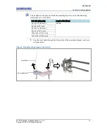
Page 26: ... attached using steel bands is 35 A to 100 A 2 Pass the steel band through the fixing hole of the mounting bracket as shown in figure below Figure 9 Fixing Mounting bracket on the Pole 1 Mounting Bracket Steel Band Pole Size Diameter Length of Steel Band 50 A 2 4 in 60 5 mm 502 mm 65 A 3 in 76 3 mm 80 A 3 5 in 89 2 mm 90 A 4 in 101 6 mm 100 A 4 5 in 114 3 mm 125 A 5 5 in 139 8 mm ...

Page 27: ...em 5G CPE Outdoor Installation Manual v1 0 15 Copyright 2018 All Rights Reserved 3 Place a mounting bracket to the pole and fix the steel band as shown in figure below Figure 10 Fixing Mounting bracket on the Pole 2 Steel Band Fixing Screw ...

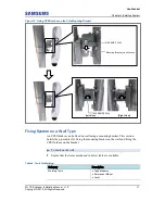
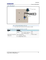
Page 28: ...tion of fasteners used to fix the mounting bracket To fix the CPE Outdoor on the pole mounting bracket 1 Ensure that the items mentioned in below table are available Table 5 Parts and Tools for Fixing CPE Outdoor on the Pole Category Description Parts Fasteners M5 L14 SEMS T25H Fastened to the unit bracket 2 EA Recommended Torque Value M5 SEMS 25 lbf in 29 kgf cm Working Tools Screw Driver Bit T25...

Page 29: ...can be fixed on wall using a mounting bracket This section details the procedures for fixing the mounting bracket on the wall and fixing the CPE Outdoor on the bracket To mark on the wall 1 Ensure that the items mentioned in below table are available Table 6 Tools for Marking Category Description Working Tools Tape Measure Permanent Maker Level M5 SEMS T25H Mounting Bracket_Hook Groove M5 SEMS T25...

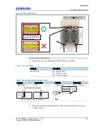
Page 30: ...d place the system on that position and then mark the positions where anchor bolts are to be fixed This reduces marking error range 2 Check the distance between the location for fixing the CPE Outdoor and the anchor bolt hole as shown in figure below Figure 13 CPE Outdoor Marking Dimensions for Wall Type 3 Place the mounting bracket on the fixing location check the level status using a level and a...

Page 31: ...s Hammer Drill Drill Bit 1 4 inch Vacuum Cleaner Table 8 Anchor Bolt Drill Bits and Hole Depth Category Anchor Bolt Drill Bits Hole Depth CPE Outdoor Φ 6 1 4 in 6 mm 1 4 in 35 mm 2 Drill anchor holes at the marked points Remove dust from the holes using a vacuum cleaner O Remove the debris from the drilled hole Anchor Hole Cross Section 35 mm 1 4 in X 1 4 in 6 mm 2 49 64 Unit in mm Marking Point I...

Page 32: ...t the items mentioned in below table are available Table 10 Parts and Tools for Fixing Mounting Bracket on the Wall Category Description Parts Mounting Bracket 1 EA Fastener M4 L25 PH Taptite Screw 4 EA Φ 6 L30 Plastic Anchor 4 EA Recommended Torque Value M4 PH Tapping Screw 13 lbf in 15 kgf cm Working Tools Torque Driver 6 22 lbf in Screw Driver Bit No 2 Hammer Drill Vacuum Cleaner 1 4 in 6 mm ...

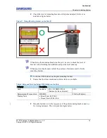
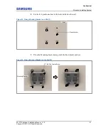
Page 33: ... All Rights Reserved 2 Fix the Φ 6 plastic anchors to the holes drilled on the wall Figure 15 Fixing Mounting Bracket on a Wall 1 3 Place the Mounting bracket along with the fixed plastic anchors Figure 16 Fixing Mounting Bracket on the Wall 2 M4 PH Taptite Screw Mounting Bracket Wall Plastic Anchor ...

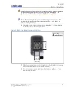
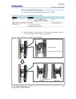
Page 34: ...ll Category Description Parts Fasteners M5 L14 SEMS T25H Fastened to the unit bracket 2 EA Recommended Torque Value M5 SEMS 25 lbf in 29 kgf cm Working Tools Screw Driver Bit T25H Torque Driver 20 90 lbf in 2 Hang the fasteners over the top groove of the wall mounting bracket and then fix it using fasteners This is depicted in figure below Figure 17 Fixing CPE Outdoor on the Wall Mounting Bracket ...

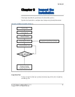
Page 35: ...he installation status Figure 18 Installation Inspection Procedure Inspection Plan Create an inspection sheet per system and select an inspector to set an inspection schedule per site NO YES Sharing Inspection Results Taking Corrective Actions On site Inspection Inspection Checklist Inspection Checklist Corrective Actions Sharing the Results of Corrective Actions and Preparing Preventive Plan Insp...

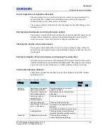
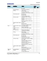
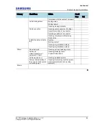
Page 36: ...n Sharing the Results of Corrective Actions and Preparing Preventive Plan After the corrective actions are all completed the inspector must share the results with the installation operator and relevant departments The inspector must prepare a preventive plan to prevent the same or similar problems from re occurring Construction Situation Checklist Table below provides the checklist to check the in...

Page 37: ...n method Power Installation status of power supply Power supply capacity Output voltage tester Installation of circuit breaker Checking circuit breaker capacity Cable specification Checking the specification Checking the limit distance Cabling Cable damage Proper installation route Compliance with the radius of curvature Cable binding status Binding status Binding interval Checking binding materia...

Page 38: ...ctor Fastening condition of a connector Checking compliance with fastening torque value Installation status of cable tag Position Marking content Checking tag installation method Checking tag installation method Others Reserved ports Checking port cap fastening status Cable inlet status Connection of equipment I O port Checking fastening status Conduit Cable Gland Cable tray and duct Checking inst...

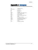
Page 39: ...s Unit BH Back Haul DC Direct Current DL DownLink GNSS Global Navigation Satellite System GPS Global Positioning System MGB Main Ground Bar PDLC Polymer Dispersed Liquid Crystal RTN Return SELV Safe Extra Low Voltage SEMS pre asSEMbled washers and screws S FTP Screened Foiled Twisted Pair TDD Time Division Duplex UL UpLink UTP Unshielded Twisted Pair ...

Page 40: ...63 5 6 6 4 M4 1 5 13 15 M5 2 8 25 29 M6 4 9 43 50 M8 12 110 127 M10 25 217 250 M12 42 372 428 Table 14 Brass Bolts Torque Value Bolt Spec Torque Value N m Torque Value lbf in Torque Value kgf cm M6 2 9 26 30 M8 6 3 56 64 Table 15 Connector Connection Torque Value Connector Torque Value N m Torque Value lbf in Torque Value kgf cm SMA connector 0 59 5 2 6 TNC connector 0 88 7 8 9 N type connector 2 ...

Page 41: ...5G CPE Outdoor Installation Manual Document Version 1 0 2018 Samsung Electronics Co Ltd All rights reserved ...

Reviews: