background image

76

Guida rapida

8. 

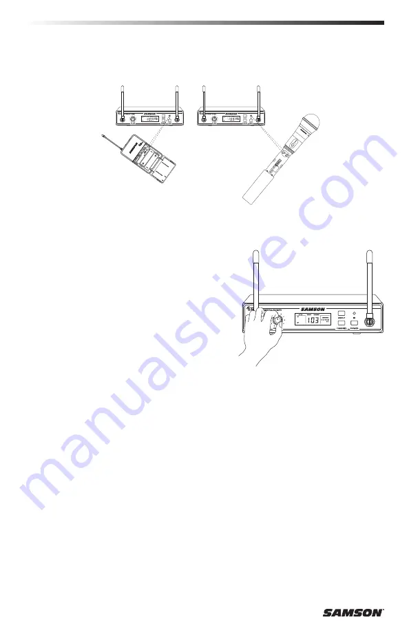
Posizionare il trasmettitore a circa 15–30 cm (6–12”) dalla parte anteriore del CR99 con l'apertura IR del 
trasmettitore rivolta verso il trasmettitore IR situato sul pannello anteriore del ricevitore CR99.

9. 

Quando la trasmissione è completa, il CR99 riceverà il segnale RF e il tone key dal trasmettitore. L'indicatore 
RF sul CR99 si accenderà, a indicare che sta ricevendo il segnale wireless dal trasmettitore. 

10.  Accendere l'amplificatore o il mixer collegati, ma abbassare 

completamente il volume. Ruotare la manopola del volume 
sul CR99 completamente in senso orario (su “10”). Questo 
è il guadagno unitario.

11.  Parlare o cantare nel microfono o, se si utilizza il trasmettitore con uno strumento collegato, suonare lo 

strumento al volume normale. Alzare lentamente il volume dell'amplificatore o del mixer fino a raggiungere 
il livello desiderato.

12.  Muoversi nell'area di esibizione per assicurarsi che la copertura sia costante ovunque.  Se il sistema presenta 

cali significativi di qualità, una ridotta portata complessiva o rumori improvvisi, modificale il canale operativo 
del sistema usando la procedura descritta in precedenza.

Quando si utilizzano impianti multipli, ciascuno di essi deve essere configurato su un canale operativo 
diverso. Configurare tutti i trasmettitori e i ricevitori aggiuntivi nello stesso Gruppo per massimizzare il 
numero di canali compatibili. Al momento di configurare trasmettitori aggiuntivi, assicurarsi di chiudere 
tutti gli altri scomparti batteria del trasmettitore per garantire che la lente IR sia coperta. Effettuare una 
ricerca canali per ciascun trasmettitore per selezionare il canale ottimale. 

Summary of Contents for Concert 99 SWC99HQ8-D

Page 1: ...OWNER S MANUAL FREQUENCY AGILE UHF WIRELESS SYSTEM...

Page 2: ...Copyright 2019 Samson Technologies V4 Samson Technologies Corp 278 B Duffy Ave Hicksville New York 11801 Phone 1 800 3 SAMSON 1 800 372 6766 www samsontech com...

Page 3: ...ch as power supply cord or plug is damaged liquid has been spilled or objects have fallen into the apparatus has been exposed to rain or moisture does not operate normally or has been dropped 15 This...

Page 4: ...d if not installed and used in accordance with the instructions may cause harmful interference to radio communications However there is no guarantee that interference will not occur in a particular in...

Page 5: ...www samsontech com for complete information about our full product line We recommend you keep the following records for reference as well as a copy of your sales receipt Receiver Serial number ______...

Page 6: ...s knob sets the level of the audio signal being output through both the balanced and unbalanced output jacks on the rear panel Reference level is obtained when the knob is turned fully clockwise to it...

Page 7: ...DC Input Connect the supplied power adapter here using the strain relief as shown in the illustration below WARNING Do not substitute any other kind of power adapter Doing so can cause severe damage t...

Page 8: ...control adjusts the trans mitter input sensitivity to work with microphone and instruments inputs For optimal performance using the included screwdriver set the input GAIN control to where you see th...

Page 9: ...supply adequate current for more than four hours WARNING Do not insert the batteries backwards doing so can cause severe damage to the CH99 and will void your warranty 5 Input GAIN Control This contr...

Page 10: ...er can see the receiver 2 With the CR99 powered off connect the included power adapter Turn the CR99 on momentarily to confirm that the unit is receiving power Then turn the CR99 power off Quick Start...

Page 11: ...o the CB99 belt pack or CH99 handheld transmitter Leave the battery compartment open 6 Turn on the power to the transmitter by pressing and holding Power switch the indicator LED will light green 7 Pr...

Page 12: ...er with a connected instrument play the instrument at normal performance level Slowly raise the volume of your amplifier or mixer until the desired level is reached 12 Walk around the performance area...

Page 13: ...are touching the rails of the rack case and are aligned with the rack rail holes Mount the receiver into the rack using the appropriate size rack screws not included To ensure equal tension and balanc...

Page 14: ...75 481 350 484 950 487 850 488 850 493 300 9 474 325 475 700 476 175 481 750 485 350 488 250 489 250 493 700 Group D 542 566MHz Channel Group 00 01 02 03 04 05 06 07 0 545 050 546 425 546 900 552 475...

Page 15: ...25 826 725 827 925 828 325 829 700 830 800 1 823 225 824 225 825 425 826 825 828 025 828 425 829 800 830 900 2 823 325 824 325 825 525 826 925 828 125 828 525 829 900 831 000 3 823 425 824 425 825 625...

Page 16: ...ut gain on the transmitter or audio source level may be too high Audio dropout The transmitter may be too far away from the receiver Move it closer to the receiver or reposition the antennas Remove an...

Page 17: ...75 x 2 44 x 0 75 96mm x 62mm x 18 5mm Weight 0 2 lb 93 g CH99 Handheld Transmitter Microphone Element Dynamic Input Gain Range 28 dB RF Power 10 mW EIRP Power Requirements Two AA LR6 alkaline batteri...

Page 18: ...quirements EN301 489 9 V1 4 1 Specific conditions for wireless microphones similar Radio Frequency RF audio link equipment cordless audio and in ear monitoring EN300 422 1 V1 5 1 Technical characteris...

Page 19: ...par exemple si le cordon d alimentation ou la fiche sont endommag s en cas de dommages en raison de renversement de liquides ou de chutes d objets dans l appa reil d une exposition la pluie ou l humid...

Page 20: ...quence et si non install et utilis conform ment aux instructions il peut causer des interf rences nuisibles aux communications radio Cependant il n y a aucune garantie que l interf rence ne se produir...

Page 21: ...avoir plus sur notre ligne compl te de produits Nous vous recommandons de conserver les informations suivantes pour r f rence ainsi que la copie de votre facture Num ro de s rie du r cepteur _________...

Page 22: ...asym triques sur le panneau arri re Le niveau de r f rence est obtenu lorsque le bouton est compl tement tourn dans le sens horaire son r glage 10 3 cran LCD Affiche les param tres de l metteur et du...

Page 23: ...en utilisant un dispositif de d charge de traction comme indiqu dans l illustration ci dessous AVERTISSEMENT Ne pas remplacer par un autre type de bloc d alimentation Cela peut provoquer de graves dom...

Page 24: ...mande de GAIN d entr e Cette commande ajuste la sensibilit d entr e de l metteur pour qu il fonctionne conjointement avec les entr es micro et des instruments Pour des performances optimales l aide du...

Page 25: ...elles ne fournissent pas un cou rant ad quat pendant plus de quatre heures AVERTISSEMENT N ins rez pas les piles vers l arri re cela peut provoquer de graves dom mages au syst me CH99 et annulera votr...

Page 26: ...adaptateur secteur fourni Allumez le syst me CR99 momentan ment pour confirmer que l appareil est sous tension Puis teignez le syst me CR99 D marrage rapide 3 Avec l amplificateur ou le mixeur hors t...

Page 27: ...de ceinture CB99 ou dans l metteur de poche CH99 Laissez le compartiment de la batterie ouvert 6 Allumez l metteur en appuyant sur l interrupteur d alimentation le voyant devient vert 7 Appuyez et mai...

Page 28: ...Augmentez lentement le volume de l amplificateur ou du mixeur jusqu atteindre le niveau souhait 12 Faites le tour de la salle de concert pour vous assurer que la couverture est coh rente dans l ensemb...

Page 29: ...rack touchent les rails du montant de rack et soient align s avec les trous dans les rails du rack Montez le r cepteur dans le rack l aide de vis de rack de taille appropri e non inclus Pour assurer u...

Page 30: ...775 481 350 484 950 487 850 488 850 493 300 9 474 325 475 700 476 175 481 750 485 350 488 250 489 250 493 700 Groupe D 542 566 MHz Canal Groupe 00 01 02 03 04 05 06 07 0 545 050 546 425 546 900 552 47...

Page 31: ...629 300 9 610 325 611 700 612 175 617 750 621 350 624 250 625 250 629 700 Groupe L 823 832 MHz Canal Groupe 00 01 02 03 04 05 06 07 0 823 125 824 125 825 325 826 725 827 925 828 325 829 700 830 800 1...

Page 32: ...aibles Le gain d entr e sur l metteur ou le niveau de la source audio peut tre trop lev Pertes de niveau audio L metteur peut tre trop loin du r cepteur Rapprochez le du r cep teur ou repositionnez le...

Page 33: ...4 x 0 75 96 mm x 62 mm x 18 5 mm Poids 0 2 lb 93 g metteur de poche CH99 l ment du microphone Dynamique Plage de gain d entr e 28 dB Puissance RF 10 mW EIRP Puissance n cessaire Deux piles alcalines A...

Page 34: ...uli res pour les microphones sans fil et autres quipements radio RF pour des liaisons audio les appareils audio sans fil et les oreillettes de liaison audio de retour EN300 422 1 V1 5 1 Caract ristiqu...

Page 35: ...sen Sie s mtliche Wartungs und Reparaturarbeiten ausschlie lich entsprechend qualifizierten Fach kr ften Eine Reparatur ist erforderlich wenn das Ger t besch digt wurde z B Besch digung von Netzka bel...

Page 36: ...anderen Funkwellen die Folge sein Dennoch ist ordnungsgem es Aufstellen keine Garantie daf r dass Interferenzen bei bestimmten Aufbauarten nicht vorkommen Falls dieses Ger t keine gef hrlichen Interf...

Page 37: ...Produktpalette finden Sie auch auf unserer Website www samsontech com Bewahren Sie die nachstehende Anleitung bitte sorgf ltig auf am Besten zusammen mit Ihrem Kaufbeleg Seriennummer des Empf ngers _...

Page 38: ...m Ger t ausgegeben wird Einen Referenzpegel erhalten Sie wenn Sie den Knopf vollst ndig im Uhrzeigersinn drehen in die Stellung 10 3 LCD Anzeige Zeigt die Einstellungen von Sender und Empf nger an 4 T...

Page 39: ...wie in der Abbildung weiter unten zu sehen WARNUNG Sie d rfen ausschlie lich das mitgelieferte Netzger t verwenden Tun Sie dies nicht so kann hierdurch Ihr CR88 schwer besch digt werden Dies kann zur...

Page 40: ...keit des vom Sender her eingehenden Signals auf die Eingangssignale von Mikrofon und Instrument abstimmen Stellen Sie zum Optimieren der Systemleistung mit einem Schraubendreher das Bedienelement zum...

Page 41: ...rie nie mals verkehrt herum einzusetzen Tun Sie dies den noch so kann hierdurch Ihr CH99 schwer besch digt werden Dies kann zur Folge haben dass Sie Ihre Garantieanspr che verlieren 5 Bedienelement Ve...

Page 42: ...et ist das im Lieferumfang enthaltene Netzger t an Schalten Sie Ihren CR99 f r kurze Zeit ein um sich zu vergewissern dass das Ger t mit Strom versorgt wird Schalten Sie nun Ihren CR99 aus Kurzanleitu...

Page 43: ...starten 5 Setzen Sie wenn der Sender ausgeschaltet ist zwei neue AA Batterien in den Tragegurt Ihres CB99 oder in den Sender in Handgr e CH99 ein Lassen Sie das Batteriefach ge ffnet 6 Schalten Sie di...

Page 44: ...Verst rkungsfaktor Eins 11 Sprechen oder singen Sie nun in Ihr Mikrofon hinein oder spielen Sie wenn Sie den Sender zusammen mit einem angeschlossenen Instrument einsetzen Ihr Instrument in gewohnter...

Page 45: ...Rackrahmens ber hren und mit den L chern der Rackschienen b ndig liegen Befestigen Sie den Empf nger im Rack Verwen den Sie hierzu Rackschrauben geeigneter Gr e nicht im Lieferumfang enthalten Befest...

Page 46: ...481 350 484 950 487 850 488 850 493 300 9 474 325 475 700 476 175 481 750 485 350 488 250 489 250 493 700 Gruppe D 542 566 MHz Kanal Gruppe 00 01 02 03 04 05 06 07 0 545 050 546 425 546 900 552 475 5...

Page 47: ...00 9 610 325 611 700 612 175 617 750 621 350 624 250 625 250 629 700 Gruppe L 823 832 MHz Kanal Gruppe 00 01 02 03 04 05 06 07 0 823 125 824 125 825 325 826 725 827 925 828 325 829 700 830 800 1 823 2...

Page 48: ...adezustand aufweisen Die Verst rkung des Eingangssignals am Sender oder der Pegel der Ton quelle sind m glicherweise zu hoch Abfallen des Tonsignals Der Sender steht m glicherweise zu weit vom Empf ng...

Page 49: ...HxLxT 96 mm x 62 mm x 18 5 mm Gewicht 93 g Sender in Handgr e CH99 Mikrofonelement Dynamisch Verst rkungsbereich Eingang Gain 28 dB Funkfrequenzleistung 10 mW quivalente isotrope Strahlungsleistung L...

Page 50: ...sanforderungen EN301 489 1 V1 9 1 Grundlegende technische Anforderungen EN301 489 9 V1 4 1 Spezifische Bedingungen f r drahtlose Mikrofone hnliche Funkger te zur bertragung von Audiosignalen und In Oh...

Page 51: ...n est n da ados se han derramado l quidos o han ca do objetos en el interior del aparato si ha estado expuesto a lluvia o humedad no funciona con normalidad o se ha dejado caer 15 No se debe exponer...

Page 52: ...de radiar energ a de radiofrecuencia y de no instalarse y ser usado de acuerdo con las instrucciones podr a provocar interferencias perjudiciales a las radiocomu nicaciones No obstante no se garantiza...

Page 53: ...productos Le recomendamos que conserve los siguientes registros como referencia adem s de una copia de su recibo de compra N mero de serie del receptor _________________________________________ N mero...

Page 54: ...v s de los jacks de salida balanceados y no balanceados que se encuentran en el panel posterior El nivel de referencia se obtiene cuando la perilla se gira completamente hacia la derecha hasta su posi...

Page 55: ...necte aqu el adaptador de corriente que se suministra usando el aliviador de tensi n tal como se muestra en la siguiente ilustraci n ADVERTENCIA No lo sustituya por ninguna otra clase de adaptador de...

Page 56: ...entrada Este control ajusta la sensibilidad de entrada del transmisor para que funcione con entradas de micr fono e instrumentos Para un rendimiento ptimo utilizando el destornillador que se incluye a...

Page 57: ...iente adecuada durante m s de cuatro horas ADVERTENCIA No inserte las pilas al rev s hacerlo podr a provocar graves da os al CH99 e invalidar a su garant a 5 Control GAIN ganancia de entrada Este cont...

Page 58: ...nte que viene incluido Encienda el CR99 moment neamente para confirmar que la unidad est recibiendo alimentaci n A continuaci n apague el CR99 Inicio r pido 3 Con su amplificador o mezcladora apagada...

Page 59: ...CB99 o el transmisor port til CH99 Deje abierto el compartimento para pilas 6 Encienda el transmisor manteniendo pulsado el interruptor Power alimentaci n el indicador LED se iluminar en verde 7 Mante...

Page 60: ...toque el instrumento a su nivel de ejecuci n normal Suba lentamente el volumen de su amplificador o mezcladora hasta alcanzar el nivel deseado 12 Camine por la zona donde se va a desarrollar la activ...

Page 61: ...est n alineadas con los orificios del riel del rack Monte el receptor en el interior del rack usan do tornillos del tama o adecuado para el rack no incluidos Para asegurar que la tensi n y el equilibr...

Page 62: ...775 481 350 484 950 487 850 488 850 493 300 9 474 325 475 700 476 175 481 750 485 350 488 250 489 250 493 700 Grupo D 542 566MHz Canal Grupo 00 01 02 03 04 05 06 07 0 545 050 546 425 546 900 552 475 5...

Page 63: ...0 629 300 9 610 325 611 700 612 175 617 750 621 350 624 250 625 250 629 700 Grupo L 823 832MHz Canal Grupo 00 01 02 03 04 05 06 07 0 823 125 824 125 825 325 826 725 827 925 828 325 829 700 830 800 1 8...

Page 64: ...a La ganancia de entrada del transmisor o el nivel de la fuente de sonido puede que sean demasiado altas Ca das de sonido El transmisor puede que est demasiado alejado del receptor Ac r quelo al recep...

Page 65: ...lt xAnch xProf 3 75 x 2 44 x 0 75 96mm x 62mm x 18 5mm Peso 0 2 lb 93 g Transmisor port til CH99 Elemento de micr fono Din mico Rango de ganancia de entrada 28 dB Potencia de RF 10 mW EIRP Requisitos...

Page 66: ...301 489 9 V1 4 1 Condiciones espec ficas para micr fonos inal mbricos equipos de emisi n de audio por radiofrecuencia RF similares dispositivos de monitorizaci n en audio sin cable y con auriculares i...

Page 67: ...ha subito danni di qualsiasi tipo ad esempio in caso di danni a livello dl cavo di alimentazione o della spina per via di danni dovuti all ingresso di liquidi o alla caduta di oggetti sull apparecchi...

Page 68: ...ra impiega e pu diffondere energia a radio frequenza e se non installata e utilizzata in conformit con le istruzioni pu causare interferenze dannose alle radiocomunicazioni Ci nonostante non vi alcuna...

Page 69: ...i raccomanda di conservare i seguenti dati come riferimento oltre a una copia della ricevuta di acquisto Numero di serie del ricevitore _________________________________________ Numero di serie del tr...

Page 70: ...segnale audio emesso tramite i jack di uscita bilanciati e non bilanciati a livello del pannello posteriore Il livello di riferimento ottenuto quando la manopola viene girata interamente in senso anti...

Page 71: ...llegare l adattatore di alimentazione in dotazione a questo livello servendosi del pressacavo come indicato nell illustrazione sottostante AVVERTENZA non servirsi di altri tipi di adattatore Questo po...

Page 72: ...normale 7 Controllo GAIN in ingresso Questo controllo regola la sensi bilit di ingresso del trasmettitore per interfacciarsi con l in gresso di microfoni e strumenti Per prestazioni ottimali usare il...

Page 73: ...i scono una corrente adeguata per pi di quattro ore AVVERTENZA non inserire le batterie al contrario per evitare gravi danni al CH99 e l annullamento della garanzia 5 Controllo GAIN in ingresso Questo...

Page 74: ...CR99 spento collegare l adattatore di alimentazione in dotazione Accendere momentaneamente il CR99 per assicurarsi che l unit sia alimentata Quindi spegnere il CR99 Guida rapida 3 Con l amplificatore...

Page 75: ...e belt pack CB99 o nel trasmettitore handheld CH99 Lasciare aperto il vano batteria 6 Accendere il trasmettitore tenendo premuto il pulsante di accensione la spia diventer verde 7 Tenere premuto il pu...

Page 76: ...e lo strumento al volume normale Alzare lentamente il volume dell amplificatore o del mixer fino a raggiungere il livello desiderato 12 Muoversi nell area di esibizione per assicurarsi che la copertur...

Page 77: ...ck non entrano in con tatto con le guide dell alloggiamento del rack e non sono allineate con i fori della guida Montare il ricevitore nel rack servendosi di viti delle dimensioni adeguate non in dota...

Page 78: ...5 481 350 484 950 487 850 488 850 493 300 9 474 325 475 700 476 175 481 750 485 350 488 250 489 250 493 700 Gruppo D 542 566MHz Canale Gruppo 00 01 02 03 04 05 06 07 0 545 050 546 425 546 900 552 475...

Page 79: ...29 300 9 610 325 611 700 612 175 617 750 621 350 624 250 625 250 629 700 Gruppo L 823 832MHz Canale Gruppo 00 01 02 03 04 05 06 07 0 823 125 824 125 825 325 826 725 827 925 828 325 829 700 830 800 1 8...

Page 80: ...se necessario Il guadagno in ingresso sul trasmettitore o il livello della sorgente au dio troppo alto Breve interruzione della trasmissione audio dropout Il trasmettitore troppo distante dal ricevit...

Page 81: ...nsioni H x L x P 96 mm x 62 mm x 18 5 mm 3 75 x 2 44 x 0 75 Peso 93 g 0 2 lb Trasmettitore Handheld CH99 Elemento microfono Dinamico Range di guadagno in ingresso 28 dB Potenza in RF 10 mW EIRP Requis...

Page 82: ...ni senza fili apparecchiature di collegamento audio a radiofrequenza RF apparati audio senza fili e auricolari di monitoraggio EN300 422 1 V1 5 1 Caratteristiche tecniche e metodi EN300 422 2 V1 4 1 N...

Page 83: ......

Page 84: ...Samson Technologies Corp 278B Duffy Ave Hicksville New York 11801 Phone 1 800 3 SAMSON 1 800 372 6766 www samsontech com...

Reviews: