Samson BR 20a Mounting And Operating Instructions Download Page 29

7-1

EB 20a_EN

November 2023 edition
Subject to technical changes

Operation

7 Operation

As soon as the commissioning/recommissioning work is com-
plete, see Chapter “6 Commissioning”, the ball valve is ready for 
operation.

Danger of burning due to hot or cold components and pipe!

Ball valve components and pipes can become very hot or very 
cold during operation and cause burns upon contact.


Ö

Let the components and pipes cool down or warm up.


Ö

Wear protective garments and protective gloves.

Danger of injury due to pressurised components and escaping 
medium!


Ö

Do not loosen the screw of the optional test connection while 
the ball valve is pressurised.

Danger of crushing due to moving actuator- and control shafts!


Ö

Do not reach into the bracket as long as the pneumatic pow-
er is connected to the actuator.


Ö

Before working on the ball valve, interrupt and lock pneumat-
ic energy and the control signal.


Ö

Vent the actuator.


Ö

Do not allow the jamming of objects in the bracket to hinder 
the operation of the actuator- and control shaft.


Ö

If the actuator- and control shaft are blocked (e.g. due to 
“seizure” if not actuated for a long period of time”), release 
the residual energy of the actuator (spring tension) before re-
leasing the blockage, see the corresponding actuator docu-
mentation.


Ö

Prior to disassembly of the actuator, bring the ball valve into 
the fail-safe position.

Danger of injury due to escaping exhaust air!

During operation, when regulating or when opening and closing 
the ball valve, exhaust air can escape, for example from the ac-
tuator.


Ö

Wear eye protection and, if necessary, hearing protection 
when working near valves.

Observe the following points during operation:


Ö

The PTFE plastic sealing surfaces tend to 

fl

 ow. After commis-

sioning and reaching the operating temperature, tighten the 
body screws with the corresponding tightening torques, see 
Table 15-1 in Chapter “15.1.1 Tightening torques”.


Ö

Tighten all 

fl

 ange connections between the pipe and ball 

valve, if necessary, with the corresponding tightening torques 
according to Table 15-2 or Table 15-3 in Chapter “15.1.1 
Tightening torques”.


Ö

The ball valve/actuator unit must be actuated with the control 
signals.

WARNING


Ö

Ball valves that were delivered from the factory with an actu-
ator are precisely adjusted. The user is responsible for any 
changes they make.


For the manual operation or manual override of the actuator 
(if present), normal manual forces are suf

fi

 cient and the use 

of extensions to increase the actuation torque is not permit-
ted.


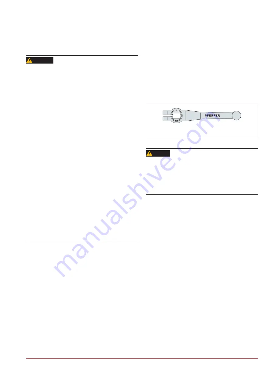
In the case of ball valves with a hand lever, the position of the 
hand lever indicates the location of the bore in the ball. The 
hand lever moves in general parallel to the bore. Special ver-
sions are to be taken from the respective order.


Hand lever 90° transverse to the pipe: Ball valve closed.


Hand lever parallel to the pipe: Ball valve open.

Figure

|

7-1: 

Hand lever

Danger of injury due to jerky operation of the ball valve!

The failure to observe these warnings can cause extreme danger 
for persons or for the pipe system.


Ö

Do not open and close the ball valve suddenly to prevent 
pressure surges and/or a temperature shock in the pipe sys-
tem.


If a ball valve leaks, observe chapter “8 Faults”.

DANGER

Summary of Contents for BR 20a

Page 1: ...Phone 02152 2005 0 Fax 02152 1580 sales pfeiffer de samsongroup com www pfeiffer armaturen com MOUNTING AND OPERATING INSTRUCTIONS EB 20a Translation of the original manual Ball valve BR 20a DIN and...

Page 2: ...safe and correct use read this EB carefully prior to use and keep it for later reference In the case of questions that go beyond the scope of this EB please contact the After Sales Service at PFEIFFE...

Page 3: ...2 Assembly of the DIN ball valve DN 150 200 3 4 3 5 3 Assembly of the ANSI ball valve 3 6 4 Shipment and on site transport 4 1 4 1 Accepting delivery 4 1 4 2 Unpacking the ball valve 4 1 4 3 Transpor...

Page 4: ...12 1 1 Ball valve in the standard version 12 1 12 1 2 Ball valve with double stuffing box 12 1 12 2 Replacing the V ring packing in the case of a ANSI ball valve 12 3 12 3 Replacing the seat ring of t...

Page 5: ...onnel The ball valve may only be disassembled dismantled assembled and commissioned by qualified specialist personnel trained in pressurised pipes who are familiar with the assembly commis sioning and...

Page 6: ...s in po tentially explosive areas Ball valves with plastic lining PFA PTFE EPDM etc through which chargeable media flows during operation must be provided with an electrostatically dissipative plastic...

Page 7: ...s media spraying medium can cause hazards It must be kept in mind that the media is usually hazardous A blind flange must be assembled on the free connecting pieces or the ball valve must be secured a...

Page 8: ...ble tools can damage the ball valve Suitable tools are required to work on the ball valve see Chapter 15 1 3 Tools Damage to the ball valve due to unsuitable lubricants Unsuitable lubricants can corro...

Page 9: ...missible op erating pressure PS and number value 7 Test pressure PT and number value The test pressure must be observed depending on the device 8 Manufacturer number from 2018 e g 381234 001 001 38 12...

Page 10: ...or DN 15 25 and NPS 1 Figure 2 2 Type plate 82149ae for DN 40 200 and NPS1 8 2 1 2 Actuator type plate See the corresponding actuator documentation 2 2 Material marking The ball valves are marked on t...

Page 11: ...he BR 20a ball valve can be selected in the following versions With a hand lever DN 15 up to 100 or NPS1 up to 4 With a manual gear With PFEIFFER rotary actuator BR 31a With rotary actuators from othe...

Page 12: ...lve material requires suitable lubricant A suitable lubri cant must be selected for grease free ball valves especially for use with oxygen For suitable lubricant see Chapter 15 1 2 Lubricant Info NOTE...

Page 13: ...the DIN version DN 15 100 Item Designation Item Designation 1 Lined body 18 O ring 2 Lined ball 19 Stuffing box lower section 3 Seat ring 20 Distance bush 4 Screw stud bolt 21 Disc spring set 5 Nut 22...

Page 14: ...the body halves 1a and 1b The seat rings may not be installed without clearance To achieve the tightness of the ball valve the seat rings must be installed in their seat with sufficient clearance If...

Page 15: ...version DN 150 200 Table 3 2 Parts list of the ball valve in the DIN version DN 150 200 Item Designation Item Designation 1 Lined body 11 Stuffing box flange 2 Lined ball 12 Screw 3 Seat ring 14 Centr...

Page 16: ...the stuffing box flange 11 Place the pre assembled stuffing box flange on the body and adjust with screws 12 Tighten the screws evenly in a criss cross pattern until a gap between 1 2 mm has formed b...

Page 17: ...n the ANSI version Table 3 3 Parts list of the ball valve in the ANSI version Item Designation Item Designation 1 Lined body 11 Stuffing box flange 2 Lined ball 12 Screw 3 Seat ring 14 Centring ring 4...

Page 18: ...see Fig 3 3 Place the centring ring 14 on the disc spring s Insert the disc spring set 9 in the centring ring until reaching the bottom ring of the V ring packing The arrangement and quantity of the d...

Page 19: ...d approved lifting equipment and load lifting equip ment whose lifting capacity corresponds at least to the weight of the ball valve including the actuator Take the weights from the respective data sh...

Page 20: ...e as examples for most valve variants On site the conditions for lifting and transporting the valve can change how ever The operator makes sure that the valve is lifted and transport ed safely WARNING...

Page 21: ...torage prior to installation the ball valve should normally be stored in a closed room where it is pro tected against harmful influences such as impacts dirt or moisture A room temperature of 25 C 15...

Page 22: ...4 4 EB 20a_EN November 2023 edition Subject to technical changes Shipment and on site transport...

Page 23: ...st air can be released to the outside protection against over pressure in the device Furthermore vents allow the intake of air protection against underpressure in the device Carry out venting on the s...

Page 24: ...permissible pressure temperature range is not sufficient for the max permissible operating conditions The limits of use are marked on the ball valve see Chapter 2 Markings on the device The permissib...

Page 25: ...fix the deformation of the pipes Screw the pipe together with the ball valve without tension After installing the ball valve open it slowly in the pipe Damage to the ball valve due to a sudden pressu...

Page 26: ...it and control command see chapter 8 Faults 5 5 2 Pressure test of the pipe section The pressure test was already performed on the ball valves by PFEIFFER Observe the following for the pressure test o...

Page 27: ...the corresponding actuator docu mentation Prior to disassembly of the actuator bring the ball valve into the fail safe position Danger of injury due to escaping exhaust air During operation when regu...

Page 28: ...6 2 EB 20a_EN November 2023 edition Subject to technical changes Start up...

Page 29: ...escape for example from the ac tuator Wear eye protection and if necessary hearing protection when working near valves Observe the following points during operation The PTFE plastic sealing surfaces...

Page 30: ...7 2 EB 20a_EN November 2023 edition Subject to technical changes Operation...

Page 31: ...ange seals If the seals are damaged replace them Leaks in the body parts The body section connection loosened Retighten the body halves with the respective tightening torque see Table 15 1 in Chapter...

Page 32: ...ot listed in the table contact the After Sales Service at PFEIFFER Spare parts must be ordered indicating all the data according to the valve marking Only original parts from PFEIFFER Che mie Armature...

Page 33: ...e and depending on the medium properties cause injuries e g scalding chemical burns Wear protective garments protective gloves and eye protec tion Do not loosen the screw of the optional test connecti...

Page 34: ...determine the cause and remedy it see Chapter 8 Malfunctions Check pipe connections and seals of the ball valve and actu ator for leaks Regular maintenance work on the ball valve is not necessary but...

Page 35: ...al energy of the actuator spring tension before re leasing the blockage see the corresponding actuator docu mentation Prior to disassembly of the actuator bring the ball valve into the fail safe posit...

Page 36: ...10 2 EB 20a_EN November 2023 edition Subject to technical changes Decommissioning...

Page 37: ...esidual medium can escape and depending on the medium properties cause injuries e g scalding chemical burns Wear protective garments protective gloves and eye protec tion Do not loosen the screw of th...

Page 38: ...11 2 EB 20a_EN November 2023 edition Subject to technical changes Removal...

Page 39: ...g 7 Check the PTFE rings of the V ring packing as well as all plastic parts for damage and in the case of doubt replace them Assemble the ball valve as described in Chapter 3 5 1 DIN ball valve assemb...

Page 40: ...12 2 EB 20a_EN November 2023 edition Subject to technical changes Repairs Figure 12 1 BR 20a ball valve...

Page 41: ...at rings may not be installed without clearance To achieve the tightness of the ball valve the seat rings must be installed in their seat with sufficient clearance If this is not possible please conta...

Page 42: ...t be accepted PFEIFFER recommends documenting the following contamina tion data in the form FM 8 7 6 Declaration regarding the contamination of PFEIFFER valves and components This form is available at...

Page 43: ...r 2023 edition Subject to technical changes Disposal 13 Disposal For disposal observe the local national and international regulations Do not dispose of old components lubricant and hazardous material...

Page 44: ...13 2 EB 20a_EN November 2023 edition Subject to technical changes Disposal...

Page 45: ...ure Equipment Directive 2014 68 EU for manually operated valves see page 14 3 Declaration of conformity for completed machinery accord ing to Machinery Directive 2006 42 EC for the ball valve with act...

Page 46: ...14 2 EB 20a_EN November 2023 edition Subject to technical changes Certificates...

Page 47: ...14 3 EB 20a_EN November 2023 edition Subject to technical changes Certificates...

Page 48: ...14 4 EB 20a_EN November 2023 edition Subject to technical changes Certificates...

Page 49: ...14 5 EB 20a_EN November 2023 edition Subject to technical changes Certificates...

Page 50: ...14 6 EB 20a_EN November 2023 edition Subject to technical changes Certificates...

Page 51: ...and 9 35 Nm DN 50 NPS2 1 to 7 25 Nm 8 and 9 30 Nm DN 80 NPS3 1 to 13 35 Nm 14 and 15 40 Nm DN 100 NPS4 1 to 14 35 Nm 15 and 16 45 Nm DN 150 NPS6 1 to 12 40 Nm 13 and 14 45 Nm DN 200 NPS8 1 to 14 50 Nm...

Page 52: ...1 3 Tools Suitable tools are required to work on the ball valve Unsuitable tools can damage the ball valve 15 2 Spare parts PFEIFFER recommends spare part sets for Commissioning and for 2 year operat...

Page 53: ...he ball valve in the DIN version DN 15 100 Pos Designation Material In the spare parts set for commissioning In the spare parts for 2 year operation 1 Lined body EN JS 1049 PTFE 2 Lined ball 1 4313 PT...

Page 54: ...150 200 Pos Designation Material In the spare parts set for commissioning In the spare parts for 2 year operation 1 Lined body EN JS 1049 PTFE 2 Lined ball 1 4313 PFA 3 Seat ring PTFE 4 Stud screw A4...

Page 55: ...signation Material In the spare parts set for commissioning In the spare parts for 2 year operation 1 Lined body EN JS 1049 PTFE 2 Lined ball 1 4313 PFA 3 Seat ring PTFE 4 Stud screw A4 70 5 Nut A4 70...

Page 56: ...6 EB 20a_EN November 2023 edition Subject to technical changes Annex 15 2 4 Spare parts of the ball valve with double stuffing box Figure 15 5 Exploded drawing of the ball valve with double stuffing b...

Page 57: ...g 1 4305 PTFE 24 O ring Viton 25 Stuffing box upper section 1 4301 26 Screw A2 70 27 Screw plug 1 4571 28 Washer A4 15 3 Service For maintenance and repair work as well as malfunctions or defects cont...

Page 58: ...n The indicated data sheets and further information are available also in English at the following address PFEIFFER Chemie Armaturenbau GmbH Hooghe Weg 41 47906 Kempen Germany Phone 49 2152 2005 0 Fax...

Page 59: ...EB 20a_EN November 2023 edition Subject to technical changes...

Page 60: ...3 edition Subject to technical changes PFEIFFER Chemie Armaturenbau GmbH Hooghe Weg 41 47906 Kempen Germany Phone 49 2152 2005 0 Fax 49 2152 1580 E Mail sales pfeiffer de samsongroup com Internet www...

Reviews: