background image

20

Samson AirLine

13.  Temporarily turn down the level of your mixer/amplifier system and turn off the power to your transmitter, leaving the receiver on.
Then restore the previously set level of your mixer/amplifier.  With the transmitter off, the receiver output should be totally silent—if it
is, skip ahead to the next step.  If it isn’t (that is, if you hear some noise), you may need to adjust the receiver Mute (squelch) control.
When the Mute control is at its minimum setting, the AirLine system always provides maximum range without dropout; however,
depending upon the particular environment your system is used in, you may need to reduce that range somewhat in order to eliminate
band noise when the transmitter is turned off.  To do so, use the provided screwdriver to rotate the Mute (squelch) control completely
counterclockwise (to the “Min” position), then slowly turn it clockwise until the noise disappears.  If no noise is present at any
position, leave it at its fully counterclockwise “Min” position (so as to have the greatest overall range available).

14.  When first setting up your AirLine System in a new environment, it’s always a good idea to do a walkaround in order to make sure
that coverage is provided for your entire performance area.  Accordingly, turn down the level of your audio system and turn on both
the transmitter and receiver.  Then, with the transmitter unmuted, restore the level of your audio system and while speaking or singing,
walk through the entire area that will need to be covered.  As you do so, observe the RF display or meter on the receiver to make sure
that it is receiving sufficiently strong RF signal (in the AR1 receiver, the “Power On / RF” LED should always remain lit steadily green;
in the UR1 and UM1 receivers, all segments of the RF Level meter should be lit).  Always try to minimize the distance between trans-
mitter and receiver as much as possible so that the strongest possible signal is received from all planned transmission points.  If you are
using an AR1 receiver in fixed installations such as A/V or corporate conference rooms, you may find it handy to mount it in the sup-
plied wall-mount holder.  In certain environments, it may be desirable to angle the receiver antenna(s) differently from the vertical
position.  Where extended range coverage is required, the Samson UR1 true diversity receiver (set to the same    channel as the trans-
mitter) should be used.  For videography applications, the Samson UM1 micro diversity receiver should be used.

If you have followed all the steps above and are experiencing difficulties, contact your local distributor or, if purchased in the
United States, call Samson Technical Support (1-800-372-6766) between 9 AM and 5 PM EST.

Setting Up and Using Your AirLine System

ENGLISH

Summary of Contents for AirLine

Page 1: ...UHF Wireless System Owners Manual Handheld Transmitter Presentation Transmitter AX1 Handheld Transmitter AL1 Presentation Transmitter AR1 Receiver UR1 Receiver UM1 Receiver SAMSON...

Page 2: ...Box 9031 Syosset NY 11791 9031 Phone 1 800 3 SAMSON 1 800 372 6766 Fax 516 364 3888 Table of Contents Produced by On The Right Wavelength for Samson Technologies Corp Copyright 2000 Samson Technologi...

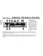
Page 3: ...r which plugs into any standard wired dynamic microphone The AirLine UHF Presentation System contains an AL1 pre sentation transmitter which contains a built in electret condenser microphone and conne...

Page 4: ...iciently strong Once battery strength is verified turn the transmitter off 4 If you are using an AX1 plug its XLR connector into a wired dynamic microphone make a good tight connection using the suppl...

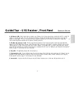
Page 5: ...necessary use the supplied plastic screwdriver to adjust the transmitter s Gain trimpot in order to increase or decrease its signal level If you are using an AL1 transmitter with the built in micropho...

Page 6: ...AR1 is at the onset of clipping that is when it is on the verge of being distorted If you see this light during operation move the microphone further away or lower the volume level of your instrument...

Page 7: ...h it can be adjusted using the supplied plastic screwdriver it should normally be left at its factory setting See the Setting Up and Using Your AirLine System section on page 17 in this manual for mor...

Page 8: ...io signal being output through both the balanced and unbalanced output jacks on the rear panel see 2 and 4 on page 8 in this manual Reference level is obtained when the knob is turned fully clockwise...

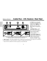
Page 9: ...h when only the left most segment is lit the incoming RF signal is at minimum strength If no segments are lit no signal is being received check to ensure that the transmitter is on and that it is set...

Page 10: ...sing the AirLine System on page 17 4 Balanced output Use this electronically balanced low impedance 600 Ohm XLR jack when connecting the UR1 to professional 4 audio equipment Pin wiring is as follows...

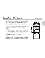
Page 11: ...ED lights red when output signal from the UM1 is at the onset of clipping that is when it is on the verge of being distorted If you see this light during operation move the microphone further away or...

Page 12: ...antennas can be folded inward for convenience when transporting the UM1 See the Setting Up and Using the AirLine section on page 17 in this manual for more information 9 DC input This jack will accept...

Page 13: ...when connecting the UM1 to professional 4 audio equipment Pin wiring is as follows Pin 1 ground Pin 2 high hot and Pin 3 low cold 15 Meter switch This three position switch determines the function of...

Page 14: ...n the direction of the arrow to turn power to the AX1 on move it away from the arrow to turn power off to conserve battery power be sure to turn the AX1 off when not in use Be sure to mute the audio s...

Page 15: ...than four hours WARNING Do not insert the battery backwards doing so can cause severe damage to the AX1 and will void your warranty 6 Microphone Input Level control trimpot Use the supplied plastic sc...

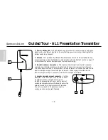
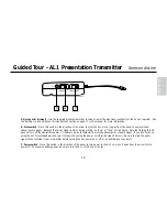
Page 16: ...al windscreen is optimized for clear crisp reproduction of speech It is active whenever the AL1 is powered on as long as there is no connection made to the lavalier microphone input connector see 4 be...

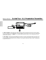
Page 17: ...turning this off does not turn off the transmitter power it is simply a way to temporarily mute the transmission of audio signal If you don t plan on using the AL1 for extended periods turn it off po...

Page 18: ...use severe damage to the AL1 and will void your warranty 9 Clip connector This clip can be used to fasten the AL1 to a lapel or shirt pocket or to the supplied lanyard The position of the clip can be...

Page 19: ...sure the Power on off switch in your transmitter is set to Off 4a If your system contains an AX1 handheld transmitter unscrew the bottom section by turning it counterclockwise and then slide it off 4b...

Page 20: ...ting that it is receiving valid RF signal and is placed and positioned correctly If your system contains either a UR1 or UM1 receiver one of the A B Receiver LEDs will light showing you whether the le...

Page 21: ...l trimpot slowly counterclockwise towards the Min position until the distortion disappears If you are using an AL1 transmitter with its internal electret condenser microphone simply move the microphon...

Page 22: ...of your audio system and turn on both the transmitter and receiver Then with the transmitter unmuted restore the level of your audio system and while speaking or singing walk through the entire area...

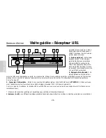
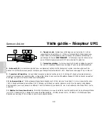
Page 23: ...teur micro AR1 ou l un des r cepteurs de la c l bre gamme Series One soit un r cepteur UR1 True Diversity destin aux applications professionnelles sur sc ne soit un r cepteur UM1 Diversity optimis pou...

Page 24: ...ux clignote alors une fois puis s teint si la pile est suffisamment puissante Une fois que la puissance de la pile a t v rifi e mettez l metteur hors tension 4 Si vous utilisez un AX1 reliez un microp...

Page 25: ...r cepteur compl tement sur la droite position qui correspond au gain unitaire 10 Chantez ou prononcez des mots dans le micro au niveau auquel ils devront l tre lors du concert ou de la conf rence tout...

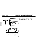
Page 26: ...arasites la sortie du r cepteur lorsque l metteur est hors tension relevez pro gressivement le potentiom tre Mute Squelch du r cepteur jusqu ce que les interf rences disparaissent 24 Samson AirLine Vi...

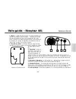
Page 27: ...en cours d utilisation loignez le microphone de la source sonore ou abaissez le volume de votre instrument ou de l metteur Voir section Configuration et utilisa tion des syst mes AirLine en page 37 de...

Page 28: ...en temps normal sur sa valeur d usine Voir section Configuration et utilisation des syst mes AirLine en page 37 9 Connecteur d alimentation Reliez ce connecteur l adaptateur secteur 12Volts 200mA fou...

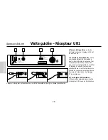
Page 29: ...s des antennes A et B En pr sence de signal l une des deux diodes s allume en vert et indique ainsi quelle antenne A gauche ou B droite est en fonctionnement Le r cepteur UR1 balaye constamment les de...

Page 30: ...r glage d usine Pour plus d information voir la page 37 de ce manuel 8 Commutateur d alimentation Utilisez cette commande pour mettre le r cepteur UR1 sous ou hors tension Lorsque le r cepteur est so...

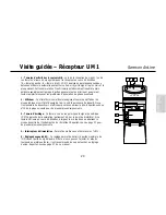
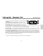
Page 31: ...afficheur pour conomiser la pile Reportez vous au n 15 de la page suivante pour de plus amples enseignements 3 T moin d cr tage Ce t moin vire au rouge lorsque le signal de sortie de l UM1 approche d...

Page 32: ...entation Ce connecteur accepte une tension continue de 6 13 Volts point chaud sur pointe masse sur corps en provenance de la cam ra vid o si disponible Reliez ce connecteur l adaptateur Samson AC300R...

Page 33: ...ermet de relier l UM1 des appareils audio professionnels 4 C blage masse blindage sur broche 1 point chaud sur broche 2 et point froid sur broche 3 15 S lecteur de fonction de l afficheur leds Ce s le...

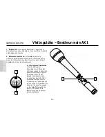
Page 34: ...ce joint n est pas n cessaire pour tous les microphones 3 Interrupteur d alimentation Le fait de d placer cet interrupteur sur la fl che met l AX1 sous tension placez le en position inverse pour le p...

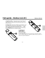
Page 35: ...sible d utiliser des piles Ni Cad recharge ables elles n offrent pas une autonomie suffisante pas plus de quatre heures ATTENTION Veillez ne pas ins rer la pile l envers sous peine d endommager gravem...

Page 36: ...lit dot d un cran anti vent en m tal optimis pour la reproduction des discours Ce microphone est activ la mise sous tension de l AL1 sauf si un micro cravate externe est reli au con necteur d entr e m...

Page 37: ...as hors tension Ce s lecteur permet simplement d interrompre temporairement la transmission du signal audio En cas de non utilisation prolong e de l AL1 il est pr f rable de le mettre hors tension au...

Page 38: ...gravement l AL1 et d annuler la garantie 9 Pince Fixez l AL1 une cravate une poche de chemise ou au cordon fourni par le biais de cette pince Vous pouvez faire piv oter cette pince dans la position so...

Page 39: ...e broche 2 point chaud broche 3 point froid Les sorties asym trique et sym trique peuvent tre utilis es simultan ment Les r glages de configuration et d utilisation de votre syst me AirLine ne prennen...

Page 40: ...teur l une des entr es audio niveau micro de l amplificateur ou de la console de mixage Privil giez la sortie sym trique sur fiche XLR car le signal qu elle d livre est peu sensible aux interf rences...

Page 41: ...L1 avec son microphone interne sachez que la qualit sonore finale d pend essentiellement du bon placement de l metteur Nous vous conseillons de le placer conform ment aux illustrations de cette page p...

Page 42: ...z simplement le microphone de votre bouche Si vous utilisez un AL1 avec un microphone cravate externe tournez lentement le potentiom tre Gain vers la droite au moyen du tournevis en plastique fourni j...

Page 43: ...ne UHF Presentation System enth lt einen AL1 Taschensender mit eingebauter Electret Kondensatorkapsel und Anschlussm glichkeit f r ein optionales Lavaliermikrofon In diesem Handbuch finden Sie eine de...

Page 44: ...mal auf und geht wieder aus sofern die Batterie ausreichend ist Schalten Sie den Sender nach der Batteriekontrolle wieder aus 4 Wenn Sie einen AX1 verwenden schlie en Sie dessen XLR Verbinder an ein M...

Page 45: ...ingang bis zum gew nschten Pegel hochdrehen Falls n tig benutzen Sie den mitgelieferten Plastikschraubenzieher zur Justierung des Gain Trimmpotis am Sender um dessen Signalpegel zu erh hen oder abzuse...

Page 46: ...fleuchtet entfernen Sie das Mikrofon von der Klangquelle oder vermindern Sie den Lautst rkepegel Ihres Instrumentes oder Senders Weitere Informationen erhalten Sie unter Konfiguration und Betrieb der...

Page 47: ...hl Sie den Regler mit Hilfe des beiliegenden Plastikschraubdrehers einstellen k nnen empfehlen wir Ihnen die werkseitige Einstellung beizubehalten Weitere Informationen erhalten Sie unter der ber schr...

Page 48: ...ie unsymmetrierten Anschl sse auf der R ckseite des Empf ngers ausgegeben wird Der Referenzpegel ist eingestellt wenn der Regler am rechten Anschlag steht Einstellung 10 3 Peak LED Diese LED leuchtet...

Page 49: ...pfangene Signal sehr schwach Leuchtet kein Segment so wird berhaupt kein Signal empfangen Vergewissern Sie sich in diesem Fall da der Sender eingeschaltet und auf den gleichen Kanal eingestellt ist wi...

Page 50: ...symmetrierten Ausgang 4 auf 20 dBm Line Pegel oder 40 dBm Mikrofonpegel ein Weitere Informationen erhalten Sie unter Konfiguration und Betrieb der AirLine Systeme auf Seite 57 dieses Handbuches 4 Aud...

Page 51: ...rke des empfangenen RF Signals anzeigt Diese Anzeige kann auch komplett desaktiviert werden um die Batterielebensdauer zu verl ngern Weitere Informationen erhalten Sie unter Nr 15 auf der nachfolgende...

Page 52: ...in da ansonsten der UM1 besch digt werden k nnte und Ihre Garantie erlischt 7 Plastikschraubdreher Dieser Schraubdreher wurde speziell f r die Einstellung des SQL Reglers s Nr 4 vorgesehen Weitere Inf...

Page 53: ...sgang symmetriert Benutzen Sie diesen elektronisch unsymmetrierten Mini XLR Anschlu wenn Sie den UM1 mit einer fachlichen 4dBu Audio Ausstattung verbinden Die Impedanz betr gt 600 Ohm Die Belegung der...

Page 54: ...Gummidichtung vor diese Dichtung ist nicht f r alle Mikrofone n tig 3 Netzschalter Power Wenn Sie diesen Schalter in Richtung des Pfeils dr cken schaltet den AR1 ein Dr cken Sie ihn in die andere Ric...

Page 55: ...tterien NiCad Akkus verwenden k nnen reduziert deren Verwendung die maximale Betriebszeit auf nicht mehr als vier Stunden ACHTUNG Legen Sie die Batterien niemals umgekehrt in das Fach ein da anson ste...

Page 56: ...e der Reden einen metallischen Anti Wind Schirm besitzt Diese Mikrofon wird durch das Einschalten des AL1 aktiviert ausser wenn ein externes Ansteck Mikrofon mit dem Mikrofon Eingangsanschluss verbund...

Page 57: ...f Bemerkung Das Mikrofon wird nicht durch den Mute Schalter ausgeschaltet Er erlaubt nur die bertragung des Audio Signals zeitweilig zu unterbrechen Wenn der AL1 eine l ngere Zeit nicht benutzt wird i...

Page 58: ...n der AL1 besch digt werden k nnte und Ihre Garantie erlischt 9 Klammer Befestigen Sie den AL1 an eine Kravatte einer Hemdtasche oder an der beiliegenden Kordel mit Hilfe dieser Klammer Sie k nnen die...

Page 59: ...nscht mittels des optionalen Samson Adapter Kits in ein Rack eingebaut werden ben tigt 1 2 HE Der UM1 kann mit Hilfe des mitgelieferten Velcro Bandes an einer Video Kamera befestigt werden 3 Ziehen Si...

Page 60: ...2 Stunden und sie sollte ausgetauscht werden Besitzen Sie ein System mit einem AR1 Empf nger sollte dessen Power RF LED von Rot auf Gr n wechseln um anzuzeigen dass er ein g ltiges RF Signal empf ngt...

Page 61: ...den Regler Trimmpoti f r den Mikrofon Eingangspegel langsam gegen den Uhrzeigersinn in Richtung Min Position bis die Verzerrung verschwindet Bei Verwendung eines AL1 Senders zusammen mit dessen intern...

Page 62: ...Dementsprechend senken Sie den Pegel Ihres Audio Systems und schalten Sender und Empf nger ein Stellen Sie dann bei nicht stummgeschaltetem Sender den urspr nglichen Pegel Ihres Audio Systems wieder h...

Page 63: ...stema AirLine UHF Presentation dispone del transmisor AL1 que contiene un micr fono condensador electreto interno y la conexi n para un micr fono lavalier opcional En este manual encontrar una descrip...

Page 64: ...posici n off lejos de la flecha y col quele una pila nueva Despu s encienda el transmisor moment neamente su piloto parpadear una vez y despu s se apagar si la pila est suficientemente cargada Una vez...

Page 65: ...micr fono a un nivel de ejecuci n normal mientras va aumentando lentamente el control de nivel de entrada audio de su amplificador o mesa de mezclas hasta que consiga el nivel que quiera Si es necesar...

Page 66: ...siempre que el AR1 est conectado a la corriente y en verde cuando el AR1 recibe una se al RF desde un transmisor 3 LED de pico Este piloto se ilumina en rojo cuando la se al de salida del AR1 est muy...

Page 67: ...punta 2 activo alto y punta 3 pasivo bajo 8 Control de anulaci n squelch Este control determina el rango m ximo que alcanza el AR1 antes de que caiga la se al audio Aunque puede ajustarlo usando el d...

Page 68: ...de si mismas para un mejor transporte del UR1 Vea la secci n de Ajuste y uso de su sistema AirLine en la p gina 77 de este manual para m s informaci n para una mayor informaci n acerca de la instalac...

Page 69: ...paratos de audio indica la fuerza de la se al UHF que est siendo recibida Cuando todos los segmentos est n encendidos la se al RF entrante estar a la potencia ptima cuando solo se ilumina el de m s a...

Page 70: ...ivel de salida audio de la salida balanceada vea 4 siguiente a 20 dBm nivel de l nea o 40 dBm nivel de micro Vea la secci n de Ajuste y uso de su sistema AirLine en la p gina 77 de este manual para m...

Page 71: ...nformaci n 3 LED de picos Este piloto luminoso LED se ilumina en rojo cuando la se al de salida del UM1 est en el l mite de la saturaci n es decir cuando est al borde de la distorsi n Si ve que se ilu...

Page 72: ...osici n vertical Las dos antenas son telesc picas y pueden ser recogidas dentro de si mismas para un mejor transporte del UM1 Vea la secci n de Ajuste y uso de su sistema AirLine en la p gina 77 de es...

Page 73: ...ste conector mini XLR balanceado electr nicamente y de baja impedancia 600 Ohm cuando conecte el UM1 a unidades de audio profesional 4 El cableado de las puntas es el siguiente punta 1 masa punta 2 al...

Page 74: ...del AR1 y su micr fono tenga en cuenta que no har falta que use este casquillo en todos los micr fonos 3 Interruptor de encendido on off Mueva este interruptor hacia la flecha para encender el AX1 de...

Page 75: ...sar pilas recargables de Ni Cad ha de tener en cuenta que no dan el flujo de corriente adecuado durante m s de cuatro horas PRECAUCION Nunca coloque la pila al rev s el hacer eso podr a producir serio...

Page 76: ...a sido optimizado para dar la mejor y m s cristalina reproducci n de la voz hablada Est activo mientras el AL1 est encendido y mientras no conecte nada en la toma de entrada de micr fono lavalier vea...

Page 77: ...activarlo Tenga en cuenta que el desactivar esto no hace que el transmisor quede apagado simplemente es una forma de anular temporalmente la transmisi n de la se al de audio Si no piensa usar el AL1 d...

Page 78: ...o podr a producir serios da os en el AL1 y har a que la garant a quedase anulada 9 Clip de sujeci n Puede usar este clip para sujetar el AL1 al bolsillo de una camisa o chaqueta o al collar que se inc...

Page 79: ...de velcro que se incluyen 3 Extienda la antena s del receptor y col quela s en posici n vertical Aseg rese de que el interruptor de encendido on off de su trans misor est ajustado a Off 4a Si su sist...

Page 80: ...iar el color del rojo al verde para indicar que est recibiendo una se al RF v lida y que est colocado y posicionado correctamente Si su sistema consta de un receptor UR1 o UM1 uno de los pilotos A B R...

Page 81: ...a la izquierda hacia la posici n Min hasta que desaparezca la distorsi n Si est usando el transmisor de petaca AL1 con su micr fono condensador electreto interno simplemente aleje un poco el micr fono...

Page 82: ...nuya el nivel de su sistema de audio y encienda tanto el transmisor como el receptor Entonces con el transmisor no anulado restaure el nivel de su sistema de audio y mientras habla o canta vaya dando...

Page 83: ...Impedance Mic 2K ohms THD 2 1 kHz deviation 15kHz Audio Frequency Response 50Hz 15kHz 3 5 dB Controls AX1 Power Switch Volume AL1 Power Switch Mute Switch Volume Input AX1 XLR female AL1 2 5mm Stereo...

Page 84: ...Sensitivity 17dBuv 4dBuv S N Ratio More than 95dB IHF A when comparing to S 0dBv More than 90dB IHF A Audio Output Level at div f15 kHz Unbalanced output 0dBv Balanced output 30 dBv Maximum Output Le...

Page 85: ...tage 12 Volts 10 Current Consumption 170 mA at all LED lights Receiving Frequency Range 801 805 MHz Sensitivity 18 dBm THD 2 Squelch Sensitivity 0 40 dBm Adjustable Selectivity 150 kHz AF Out Ratio 60...

Page 86: ...3 pc Peak LED lighting point AF output level approx 4 dB Controls Audio Level swtitch Squelch volume Headphone volume Meter function switch Operating Temperature 0 C 55 C Operating Voltage AC adapter...

Page 87: ...Mid frequencies 85 Samson AirLine Appendix A Channel Plan Channel Frequency U1 801 375 MHz U2 801 875 MHz U3 803 125 MHz U4 803 750 MHz U5 804 500 MHz U6 804 750 MHz...

Page 88: ...to be rotated and can be removed to reveal the exit hole See page 16 in this manual for further instructions For clarity all the illustrations in this Appendix show the AL1 with the tie clip removed...

Page 89: ...tration above Insert the lanyard clip into the AL1 tie clasp until it snaps 4 The AL1 should rest approximately in the middle of the chest of the person speaking see illustration above To increase sig...

Page 90: ...d licensability depends on the user s classification application and frequency selected This device complies with RSS 210 of Industry Science Canada Operation is subject to the following two condition...

Reviews: