22
EB 3131-1 EN
Operation
9
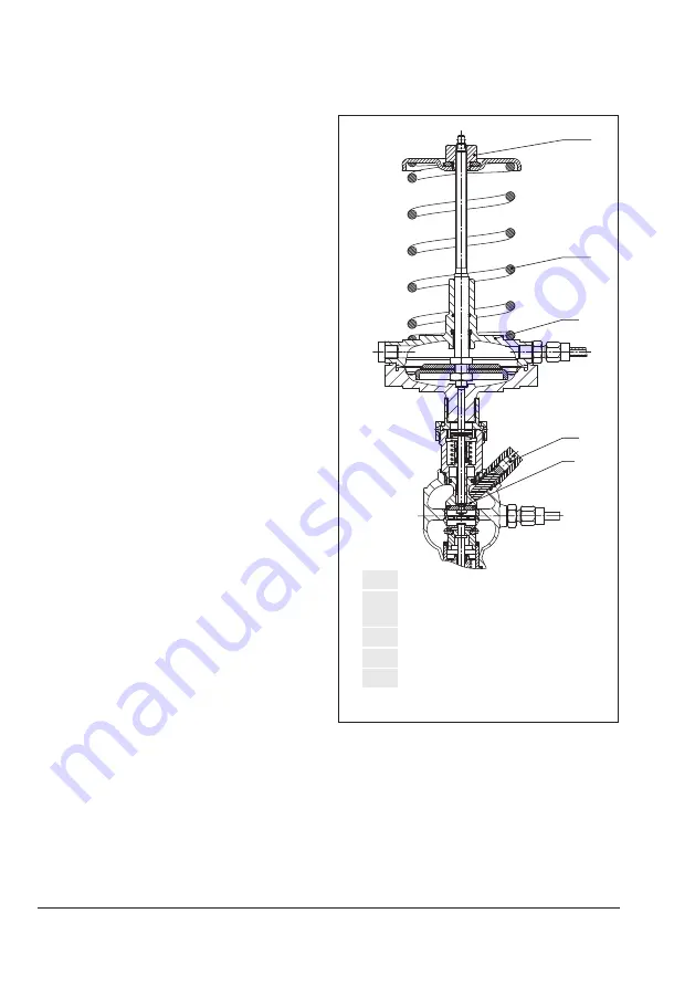
Restriction
9.1
Set point screw (flow rate,
SW 4)
15 Pressure control actuator
15.1 Set point adjuster (pressure)
15.4 Set point spring (pressure)
15
9.1
9
15.4
15.1
Fig. 6:
Flow control · DN 15 and 25
6 Operation
6.1 Adjusting the set points
6.1.1 Flow control
Î
Adjust the maximum differential pressure
at the regulator (see section 6.1.2).
Î
Completely open the control and shut-off
valves or a bypass valve in the plant.
DN 15 and 25
1. To place the restriction (9) in the end po-
sition, relieve the tension from the set
point spring (15.4) at the pressure con-
trol actuator (15) by turning the set point
adjuster (15.1) counterclockwise (
) as
far as it will go.
2.
Use a suitable tool (Allen key, SW 4) to
turn the set point screw (9.1) clockwise
(
) as far as it will go.
3. Fully load the set point spring (15.4) at
the pressure control actuator (15) by
turning the set point adjuster (15.1)
clockwise (
) as far as it will go.
4.
Refer to Fig. 8 to find out how many
turns are required to set the flow rate.
5.
Use a suitable tool (Allen key, SW 4) to
turn the set point screw (9.1) by the re-
quired number of turns. Turn it counter-
clockwise (
) to open the restriction. The
flow rate rises.
6. Guide the wire through the lead-seal
hole and lead-seal it to fix the adjusted
flow rate.
DN 40
1. To place the restriction (9) in the end po-
sition, turn the knurled nut (9.2) clock-
wise (
) as far as it will go.
2. Fully load the set point spring (15.4) at
the pressure control actuator (15) by
Summary of Contents for 46-7
Page 35: ...EB 3131 1 EN 35...


