background image

www.larius.com

16

L400

REV.

 02 - 02/2020 - Cod. 150085

ROUTINE MAINTENANCE

R

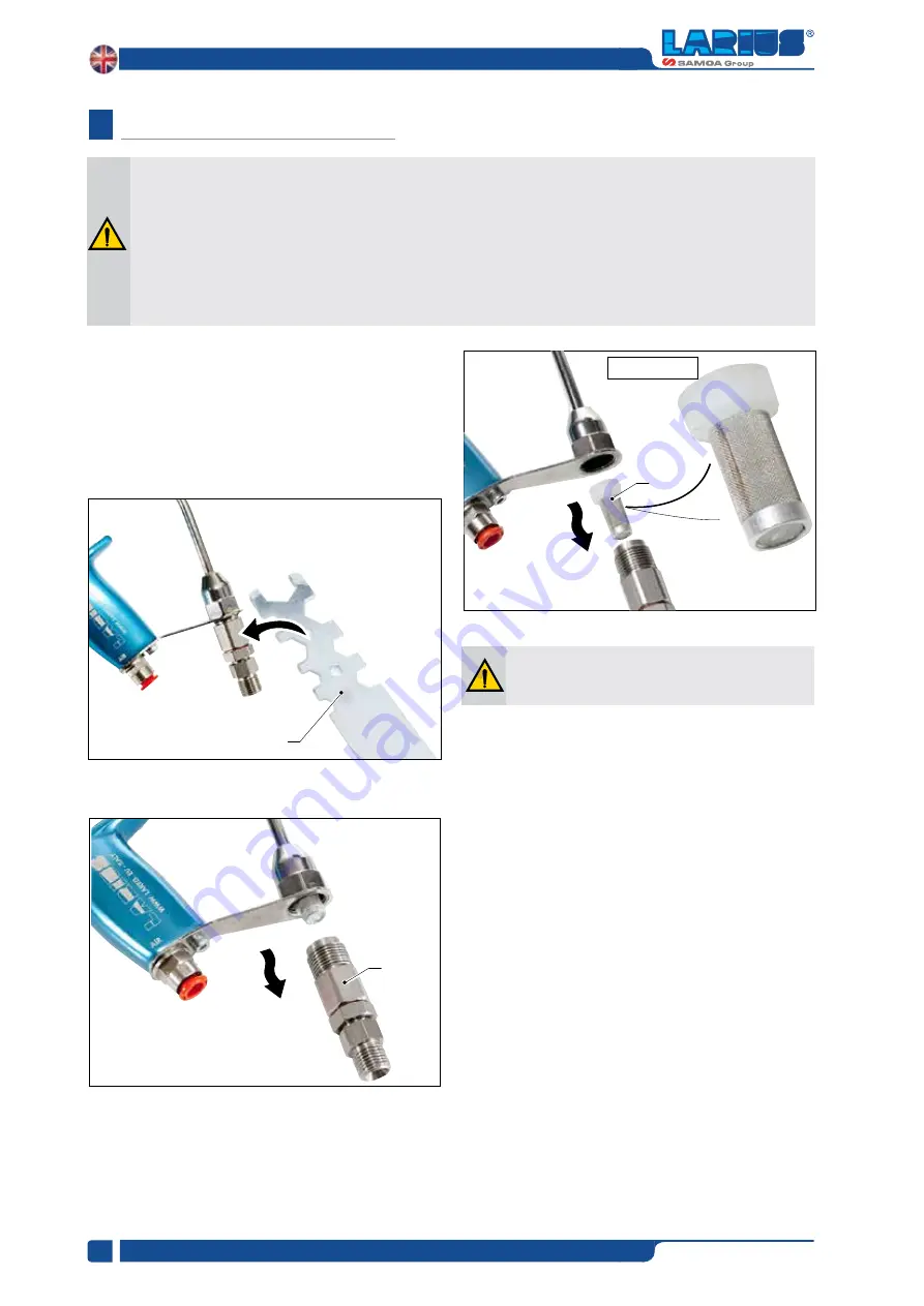
• Remove the product filter 

(R3) 

and replace it with a new one.

NOTE: should the filter be blocked, use the pliers to remove it easily.


• Insert the new filter (

R3

) as shown in the picture.

• Duly place the fitting in its seat

 (R2)

.

On first use of the gun check for any leaks of 
product from the ring (R2). 

To reduce the risk of serious injury, including fluid injection or splashing the eyes or on the skin:

•  Always follow the PRESSURE DISCHARGING PROCEDURE (see page 11) before checking, adjusting, cleaning 

or repairing the gun or any part of the system.

•  After adjusting or servicing the gun, if fluid does flow, the gun is not assembled properly or the trigger lock is 

damaged. Reassembled the gun or return it to your nearest distributor. Do not use the gun until the problem is 
corrected. 

•  When removing the gun from the hose, be sure to hold the inlet fitting securely to avoid loosening from the gun 

body.

REPLACE PRODUCT FILTER

ATTENTION

for further details, please refer to the drawing 

on page 22. To replace the product filter, proceed as follows:

• Use the provided wrench 

(R1)

.

• Loose and remove the fitting (R2)

R1

R2

R3

Product filter

Summary of Contents for LARIUS L400

Page 1: ...Air assisted airless manual spraying gun L400 w w w l a r i u s c o m REV 02 02 2020 Cod 150085 English OPERATING INSTRUCTIONS ...

Page 2: ...twork of distributors and resellers and is a guarantee of Total Product Quality in the industrial plastics construction wood and road marking sectors Due to a constant product improvement programme the factory reserves the right to modify technical details mentioned in this manual without prior notice This manual is to be considered as an English language translation of the original manual in Ital...

Page 3: ...UTINE MAINTENANCE replace product filter p 16 replace product gasket p 17 replace coupling group p 19 replace air valve gasket p 20 replace bushing gasket p 22 replace product house gasket p 23 AIR ASSISTED AIRLESS MANUAL GUN L400 p 26 SUPER FAST CLEAN NOZZLE p 28 AIR ASSISTED AIRLESS NOZZLES p 29 nozzles top spraying clean p 29 base mist clean 2 p 29 KIT AND SPARE PARTS p 29 LONG FILTER MATERIAL ...

Page 4: ... carry out the decompression procedure explained in this manual and prevent any risk of the equipment starting unexpectedly Report any risk of chemical reaction or explosion if this warning has not been given IF PROVIDED There is a risk of injury or serious lesion related to contact with the jet from the spray gun If this should occur IMME DIATELY contact a doctor indicating the type of product in...

Page 5: ...over time Components are easy to assemble and disassemble during maintenance operations All guns offer the possibility to open or close the product recirculation choose between two products inlets Air assisted airless Mist clean The two systems are fully interchangeable with no need to modify the body of the gun provide quick couplings to speed up the connection of the gun to the air hose provide ...

Page 6: ... Reduced maintenance Long working life The nozzle does not have to be removed for cleaning but simply turned 180 based on the same principle as Fast Clean WORKING PRINCIPLE D TECHNICAL CHARACTERISTICS E Maximum fluid pressure 250 bar 25 MPa Maximum working air pressure 7 bar 0 7 Mpa Guns body Alluminium Maximum working fluid temperature 50 C Wetted parts stainless steel carbide polyethylene chemic...

Page 7: ...www larius com 7 L400 REV 02 02 2020 Cod 150085 187 147 240 F a Dimensions and overall l400 gun DIMENSIONS AND OVERALL F ...

Page 8: ...ES OR AT OTHER PEOPLE THE CONTACT WITH THE CASTING CAN CAUSE SERIOUS INJURIES INCASEOFINJURIESCAUSEDBYTHEGUNCASTING SEEK IMMEDIATE MEDICAL ADVICE SPECIFYING THE TYPE OF THE PRODUCT INJECTED NEVER UNDERVALUE A WOUND CAUSED BY THE INJECTION OF A FLUID ALWAYS DISCONNECT THE SUPPLY AND RELEASE THE PRESSURE IN THE CIRCUIT BEFORE PERFORMING ANY CHECK OR PART REPLACEMENT OF THE EQUIPMENT NEVER MODIFY ANY...

Page 9: ...FACE SHIELDS TAKE PROPER SAFETY MEASURES FOR THE PROTECTION OF HEARING IN CASE OF WORK NEAR THE PLANT DO NOT POINT THE GUN UPWARDS DURING CLEANING OPERATIONS The high speed of the product in the hose can create static electricity through discharges and sparks It is suggested to earth the equipment The pump is earthed through the earth cable of the supply The gun is earthed through the high pressur...

Page 10: ... 02 2020 Cod 150085 DESCRIPTION OF THE EQUIPMENT I Pos Description 1 Head 2 Locking ring nut 3 Safety lever 4 Gun body Pos Description 5 Gun air adjusting screw 6 Air inlet fitting 7 Trigger 8 Material inlet fitting 8 1 3 4 5 7 2 6 ...

Page 11: ...sure Discharging Procedure as hereby described beforecleaningorremovingthefluidnozzleorservicing any system equipment MEDICAL ALERT FLUID INJECTION WOUNDS If any fluid appears to penetrate your skin get EMERGENCY MEDICAL CARE AT ONCE DO NOT TREAT AS A SIMPLE CUT Tell the doctor exactly what fluid was injected This is a high pressure dispensing gun Fluid dispensed under high pressure could be injec...

Page 12: ...y your system Never exceed the maximum working pressure of your gun model EQUIPMENT MISUSE HAZARD L The maximum working pressure of the gun is 110 bar Do not exceed the maximum Working pressure HOSE SAFETY M Before each use check the entire hose for cuts leaks abrasion bulging cover or damage or movement of the hose couplings Do not pull on hoses to move equipment Do not use fluids or solvents whi...

Page 13: ...a properly grounded fluid hose and pump Fluid supply container according to local code All solvent pails used when flushing according to local code Useonlymetalpails Donotplacethepailonanon conductive surface such as paper or cardboard which interrupts the grounding continuity To maintain grounding continuity when flushing or relieving pressure always hold a metal part of the gun firmly to the sid...

Page 14: ...y after performing all the SETTING UP operations described above To reduce the risk of serious injury including fluid injection or splashing in the eyes or on skin always follow the PRESSURE DISCHARGING PROCEDUREwheneverthedispensingequipment is shut off when checking or servicing any part of system when installing or changing nozzles and whenever you stop dispensing Alwaysengagethetriggerlockwhen...

Page 15: ...randpaintcomingout of the gun must leave a spraying trace without tails At this point the product will flow until reaching the gun and you can start working TRIGGER LOCK DISENGAGED Todisengagethetriggerlock Q2 rotatethetriggerlockbackward TRIGGER LOCK ENGAGED To engage the trigger lock release the trigger and rotate the trigger lock Q1 forward Neverpointthespraygunatyourselvesoratother people The ...

Page 16: ...ARGING PROCEDURE see page 11 before checking adjusting cleaning or repairing the gun or any part of the system After adjusting or servicing the gun if fluid does flow the gun is not assembled properly or the trigger lock is damaged Reassembled the gun or return it to your nearest distributor Do not use the gun until the problem is corrected When removing the gun from the hose be sure to hold the i...

Page 17: ...ith the provided wrench R7 Use the provided wrench R11 to unscrew the nut R9 and the pivot R10 and disassemble the trigger R8 Holdthenut R12 withpointedpliers R13 Unscrewtheneedle R14 and remove the bushing R15 During this operation check the neddle R14 and the needle tip R16 whose surface shall not be damaged or worn Replace it if necessary Payattentiontothedirectionofthebushing R15 in order to g...

Page 18: ...ide the ga skets group Positiontheproductgasketsgroup R22 insidethegun making sure to lubricate the threads with grease Place the needle R23 inside the gun making sure to lubricate the surface with grease Duringassembling payattentiontothedirection of the gasket R21 which should be placed with the sealing lip facing inward see picture below R21 R20 R18 R19 R17 R22 R23 R21 R20 ...

Page 19: ...ed REPLACE THE COUPLING GROUP ATTENTION for further details please refer to the drawing on page 26 To replace the coupling group proceed as follows Remove the ring nut R35 Hold the trigger R36 with your hand unscrew the coupling group R37 witht he provided wrench R38 and replace with a new spare part R39 At this point the procedure for the coupling group replacement is completed Reassemble the gun...

Page 20: ...nd the spring R43 and R44 Use the provided wrench R48 to unscrew the nut R46 and the pivot R47 and disassemble the trigger R45 Remove the air valve R49 by using poined pointed pliers R50 Remove the ring nut R51 and the coupling R52 During this operation make sure that the needle is not damaged or worn R40 If necessry re place it as described in the previous paragraph Replace product gasket R40 R39...

Page 21: ...60 making sure it is duly placed as shown in the picture Place the gaskets ring R61 inside the air valve R62 Place the air control needle R63 inside the air valve R64 and assemble the whole group insde the gun body R65 Before inserting the air valve lubricate the valve surface with grease P64 as shown in the pre vious picture Duringassembling payattentiontothedirection of the gasket P57 which shou...

Page 22: ...emble the trigger R73 Hold the trigger and reassemble the coupling R78 and the ring nut R77 At this point the procedure for the air valve gasket replacement is completed REPLACE THE BUSHING GASKET FOR AIR ADJUSTMENT NEEDLE ATTENTION for further details please refer to the drawing on page 26 To replace the air valve gasket porceed as follows Unscrew the hex nut of the air regulator R79 with the pro...

Page 23: ...re for the bushing gasket replacement is completed Reassemblethegunfollowingthepreviousprocedure in reverse order REPLACE THE PRODUCT HOUSE GASKET ATTENTION for further details please refer to the drawing on page 22 To replace the product house gasket porceed as follows Remove the screw P88 of the house supporting bracket by using the suitable wrench P89 Remove the revolving fitting P90 Use a suit...

Page 24: ...he hex nut R98 with your hand without overtightening Fasten with your hand the screw R99 and the revolving fitting R100 without overtightening Securely fasten with the provided hex wrench R101 Securely fasten the screw R102 and the revolving fitting R103 At this point the procedure for the product house gasket replacement is completed R96 R94 R95 R97 R98 R98 R100 R99 R99 R100 R101 R103 R102 ...

Page 25: ...www larius com 25 L400 REV 02 02 2020 Cod 150085 T h i s p a g e i s i n t e n t i o n a l l y l e f t b l a n k ...

Page 26: ...NUAL GUN L 400 WARNING Always indicate code and quantity for each part required S 1 2 3 4 5 6 7 8 9 10 11 12 13 14 15 16 17 18 19 20 21 22 23 24 25 26 27 28 32 29 31 33 34 19 35 36 37 38 30 Standard version 16A 16A position must be combined with the use of Mist clean system ...

Page 27: ...l house 24 270 Filter 100 mesh 25 21870 Fitting filter holder 26 7021 Gasket 27 11155 Revolving fitting 28 5338 Screw 29 4006 Quick connection 30 12572 O ring 31 21863 O ring 32 21877 Fitting 33 21865 O ring 34 21823 Needle guide 35 21812 Gasket 36 21860 O ring 37 21858 Tool 38 21890 Tool 4a 4b 4c 5a 5b 5c 9a 9b 9c 9d 15a 15b 8a 8b 2a 2b 5d POS PART NO DESCRIPTION 2a 21873 Air Cap 2b 21874 Nozzle ...

Page 28: ...SFC 13 20 0 80 SFC 13 40 SFC 13 60 SFC 15 20 1 10 SFC 15 40 SFC 15 60 SFC 17 20 1 41 SFC 17 40 SFC 17 60 SFC 19 20 1 77 SFC 19 40 SFC 19 60 SFC 21 20 2 15 SFC 21 40 SFC 21 60 Size Rate l m 200 BAR SFC 23 20 2 57 SFC 23 40 SFC 23 60 SFC 25 20 2 90 SFC 25 40 SFC 25 60 SFC 27 20 3 50 SFC 27 40 SFC 27 60 SFC 27 80 SFC 29 20 4 30 SFC 29 40 SFC 29 60 SFC 29 80 SFC 31 40 4 83 SFC 31 60 SFC 31 80 SFC 33 4...

Page 29: ...0 TSC 11 40 TSC 13 20 TSC 13 40 TSC 13 60 TSC 15 20 2 a b c Size TSC 15 40 TSC 15 60 TSC 17 20 TSC 17 40 TSC 17 60 TSC 19 20 TSC 19 40 TSC 19 60 TSC 21 20 TSC 21 40 2 a b c Size TSC 21 60 TSC 23 20 TSC 23 40 TSC 23 60 TSC 27 20 TSC 27 40 TSC 27 60 TSC 31 40 W BASE MIST CLEAN 2 Code Description 21900 Mist clean base KIT AND SPARE PARTS X Code Description 21910 Complete SFC nozzle coupling 21915 Com...

Page 30: ...filter material house 3 33010 Copper gasket 4 11017 Spring 5 21868 Fitting 6 7021 Copper gasket Pos Code Description 7 11155 Revolving fiting 8 21911 Long filter 30 mesh green 9 21912 Long filter 60 mesh white 10 21913 Long filter 100 mesh yellow 11 21914 Long filter 200 mesh red NOTE positions indicated with are not included in the kit 1 8 2 4 5 6 7 3 11 8 9 10 ...

Page 31: ...ce the gaskets Fluid flow stops or it comes out slowly Nozzle dirty or clogged Clean or replace it Materialleaksfromthegasketpressing screw Gasket loosened or worn Tightenthegasketpressingscreworchangethegasket Atomization imperfect Nozzle worn Replace it Spraying jet irregular Insufficient fluid feed Air in the paint feed line Nozzle worn Adjust the fluid outflow or fill the fluid feed can Check ...

Page 32: ... 21340 AIR ASSISTED AIRLESS automatic gun L200 with side inlets complete with Mist Clean 2 base for Super Fast Clean or Top spraying Clean tip ALLUMINIUM Code 21344 INOX Code 21342 AIR ASSISTED AIRLESS automatic gun L201 with rear inlets for Air assisted airless tip ALLUMINIUM Code 21346 INOX Code 21341 AIR ASSISTED AIRLESS automatic gun L201 with rear inlets complete with Mist Clean 2 base for Su...

Page 33: ...Code 21801 Airless spraying gun AT250 complete with Super Fast Clean base Code 11200 Airless gun PLA cm 130 complete with Super Fast Clean base Code K11421 Automatic gun MA98L low pressure Code 11300 airless LA95 GUN Automatic high pressure Code 11700 Gun RAC2 Automatic low pressure Code 14100 Airless spraying gun L91X complete with Super fast Clean base Code 11130 Airless spraying gun AT300 compl...

Page 34: ...LARIUS srl Via Antonio Stoppani 21 23801 Calolziocorte LC ITALY TEL 39 0341 621152 Fax 39 0341 621243 larius larius com www larius com ...

Reviews: