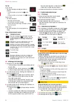
Installation
User’s manual — 2900453/2
5
EN
3)
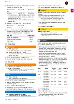
Check that the dynamic pressure of the machine feed water is
within the following range of values:
⇒
If the water pressure is higher than the maximum indicated,
install a pressure regulator to set the pressure between 2.5
and 4
bar (250 and 400
kPa).
⇒
If the water pressure is below the minimum value, install a
back-up valve.
4)
Check the following values of the feed water flow rate:
5)
[Models without drain pump]
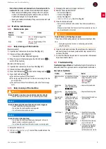
Connect the drain pipe with an
outer diameter of 30
mm to the drain line [
/A]. For the
maximum drain height, observe the following values:
2.3
Unpacking
1)
Remove the packaging that protects the machine.
2)
Lower the machine from the pallet on which it is mounted.
2.4
Assembly
1)
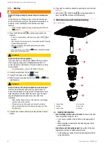
Screw the legs to the base of the machine.
2)
Adjust the height of the legs so that the machine is stable and
level with the ground.
3)
Place the machine at the installation site.
4)
Check that the tap water pressure is within the parameters
specified in the previous chapter (use of the pressure gauge).
5)
Connect the water outlet hose to the drain point.
6)
Connect the water supply hose to the mains water point.
7)
Insert the detergent and rinse aid inlet hoses into the corre
-
sponding bottles.
2.5
Electrical connection
1)
Before plugging in the machine, make sure that the mains volt
-
age matches the voltage indicated on the machine nameplate.
2)
Set up the machine's electrical connections, depending on the
model and configuration of the machine.
3)
Disconnect the electrical power supply: unplug the circuit-
breaker on the electrical panel corresponding to the external
power supply socket of the machine.
4)
Make the electrical connection according to the type of model
and electrical configuration of your machine, as explained in the
attached document "Electrical diagram" for each case.
5)
Prepare a residual current circuit-breaker with a sensitivity of
30
mA and a magneto-thermal circuit-breaker as described in
the following table:
2.6
First start-up
1)
Turn on the water stopcock.
2)
Switch on the circuit-breaker of the electrical panel correspond
-
ing to the external power supply socket of the machine.
3)
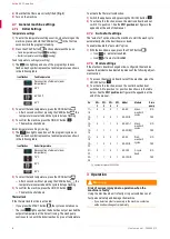
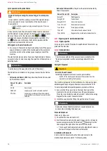
Place the overflow pipe in position
Dynamic water pres
-
sure
Minimum value
Maximum value
All models
2
bar (200
kPa)
4
bar (400
kPa)
Water flow rate
Minimum value
All models
15 L/min
Drain height
Maximum value
Models with drain pump (B)
1,000
mm
Dome models without drain pump
500
mm
Other models
90
mm
⚠
Warning
Risk of trapping hands
There is a high risk of trapping your hands if you lift the ma
-
chine onto the base and place it on the ground.
– To move the machine from one place to another, hold the
machine from the sides.
⚠
Warning
Risk of serious accidents if the machine cannot be
disconnected or turned off
– When installing the machine, make sure the operator will be able
to reach the switch and plug without difficulty.
Notice
Risk of water leakage
– Before installation, turn off the water stopcock.
Notice
Risk of hose clogging and/or choking
– Avoid making reductions with the hose when installing.
⚠
Caution
Risk of irritation due to chemical exchange and foam
release
If you insert the detergent and rinse aid inlet hoses into the
wrong bottles, the machine will produce excessive foam.
– Pay attention to the labelling on the chemical hoses before
inserting the hoses into the corresponding bottles.
⚠
Caution
Electric shock hazard
– The machine must be connected to earth.
– The machine has an external earth-connection screw
with the symbol shown;
ℹ
Information
The connections may only be accessed by qualified personnel
Model
Voltage
Cable sec
-
tion
Total
Power
Protection
AX-40
230V/50Hz/1~
220V/60Hz/1~
3 x 2.5 mm2
2.74 kW
16 A 2P
AX50
230V/50Hz/1~
220V/60Hz/1~
3 x 2.5 mm2
3.35 kW
16 A 2P
AX-100
230V/50Hz/1~
220V/60Hz/1~
3 x 6.0 mm2
6.75 kW
36 A 2P
400V/50Hz/3N~
380V/60Hz/3N~
5 x 2.5 mm2
6.75 kW
20 A
(3P+N)
230V/50Hz/3~
220V/60Hz/3~
5 x 6.0 mm2
6.75 kW
25 A 3P
Summary of Contents for AX-50
Page 12: ...Active AX Technical specifications 12 User s manual 2900453 2...
Page 36: ...Active AX 36 Manual de usuario 2900453 2...
Page 37: ...Active AX 12 2900453 2...
Page 41: ...Active AX 8 2900453 2 4 5 6 3 4 1 1 PROG START 2 5 4 3 4 1 60 1 4 2 5 3 6 1 2 3 4 5 6...
Page 47: ......
Page 48: ...10 22 2900453 2 ER 0437 1 96 AX 40 AX 50 AX 100 ACTIVE AR...


