background image


Version B     June, 2020 

25 

MagnaRam-SK  


6 Operation: 

See Control Box 65-3290-00 Operation section for description and functions of the control panel. 

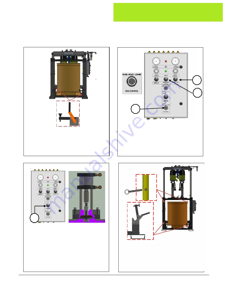
6.1 Unloading 

Material. 


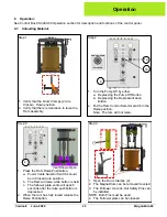
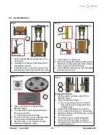
Step 1 


1.  Verify that the Drum Clamps (2) are 
 

Closed – Down position. 

2.  Verify that there is clearance to raise the 
 Ram 

assembly. 

Step 2 


1.  Turn the Pump Off by either. 
 

a.  Depressing the Pump Off Button  


b.  Depressing the Depressurization  

  Button. 
2.  Put the Ram Control Selector switch in the 
 Raise 

position. 


Note:  The ram will not raise. 

1a


1b


2


Step 3 


       Vent 

Shown 

Open 

1.  Press the Ram Raise Pushbutton. 
 

a.  Power Vents Selector Switch should  


be in Closed Auto  position. 


b.  The Ram will raise while button is held.  


c.  The follower plate vents will open 5  


seconds after the raise pushbutton is 

  depressed. 
2.  When the ram has fully raised release the 
 Raise 

Pushbutton. 


2


Step 4 


1.  Open the Drum Clamps (2). 
2.  The MagnaDrum can be removed/covered. 
3.  The Follower Up Lock-Out Safety Pins can 
 be 

installed. 

NOTE: Both Pins must be used. 
4.  The Follower plate can be cleaned. 

Operation 

Summary of Contents for Magna-Ram

Page 1: ...USER MANUAL Magna Ram 300 Gallon Elevator and Controls...

Page 2: ...l na com Service Phone 734 979 0100 24 Hour Hotline 877 726 3795 Email tservice exel na com Training Phone 734 979 0100 Email exel training exel na com All communication or reproduction of this docume...

Page 3: ...ommercial Products 10 1 11 General Electrostatic Systems 11 1 11 1 Manual Electrostatic Systems 12 2 Magna Ram 13 2 1 Complete Magna Ram with double ball pumps 14 2 1 1 Double Ball Pumps 15 3 Specific...

Page 4: ...6 Control Box Components 39 7 6 1 Control Box Inside components 40 7 6 2 Control Box Top 41 7 6 3 Control Box 65 3290 00 Operation 42 7 6 4 Control Box Door Layout 43 7 6 5 Control Box Subplate Layout...

Page 5: ...ort Check Valve 62 3213 02 1 1 4NPT Plated 67 7 17 Pump Installation Assembly 62 3244 01 105mm 68 7 18 Pump Installation Assembly 62 3244 03 80mm 69 7 19 Depressurization Kit 65 3056 04 70 7 19 1 Depr...

Page 6: ...MES KREMLIN Inc training course and become familiar with the proper operation of the system All persons involved with electrostatic or non electrostatic finishing operations should carefully read and...

Page 7: ...and certified before operating any equipment Improper use of system equipment may result in injury This equipment is for professional use only Equipment should be used only for what it has been desig...

Page 8: ...cedure and depressurize the air and fluid circuits before attempting to carry out any work This includes collecting of fluids cleaning troubleshooting and preventative maintenance procedures Whenever...

Page 9: ...um or zinc The non compliance with the instruction has the capacity to cause explosion hazards which may result in fatal injuries 1 8 Lockout Energy Sources Lock out any source of energy and relieve d...

Page 10: ...ng of hoses Always install pneumatic and material lines with sweeping soft bends Before production verify that all fittings are properly fastened as to avoid possible leaks Routinely check the hoses f...

Page 11: ...ectrostatic atomizing heads should be effectively and permanently supported on suitable insulators and should be effectively guarded against accidental contact or grounding 4 An automatic means should...

Page 12: ...type and be designed to be intrinsically safe and not produce a spark of any sufficient energy to ignite vapor air or powder air mixtures nor result in an appreciable shock hazard upon contact with a...

Page 13: ...d unloading and even drum material pressure Drum Centering Cradle Provides positive drum alignment for easier drum changes Dual Pumps packages Include many Pressure Flow ranges for a wide range of mat...

Page 14: ...RH Steel Ram w 2B 30 980 Pump LH Steel 668 070 203 Magna Ram 2 w Crossover 2B 30 980 Pumps Standard Fluid Piping Steel 668 070 104R 668 070 104L Ram w 2B 30 980 Pump RH S S Ram w 2B 30 980 Pump LH S...

Page 15: ...nge of ratio and volume are available Ratios 4 1 80 1 Volume 79cc 1000cc Note All specifications are per single pump Other selections are available More details are in the Master Pump Catalog This man...

Page 16: ...formation for actual requirements Air SCFM Ram 50 SCFM Note Ram and Pump are not at full flow at same time Air Inlet Connection 1 in 16JICM Clean Dry Free of Oil Liquids 5 Micron Filter Max 87 Psi 6 b...

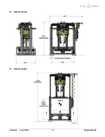
Page 17: ...Version B June 2020 17 MagnaRam SK 3 2 Ram Retracted 3 3 Ram Extended...

Page 18: ...Version B June 2020 18 MagnaRam SK 3 4 Load Height...

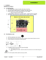
Page 19: ...d e Use anchors large enough that exceed the force of elevator 3 4 1in anchors 4 2 Grounding the pump a Use the supplied ground connector b Unscrew the locknut A Place the ground wire D between the B...

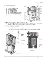
Page 20: ...ction 1in NPT a Depending on the pump package selected the air requirement can range from 200 480cfm at 87 psi 6bar Select the size and length of the air supply hose accordingly 3 Open P1 and P2 Ball...

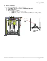
Page 21: ...port a Verify that the outlet hose is within the pressure rating of the pump b Outlet Port is 24JICM c Run the elevator up and down i Verify that there are no clearance issues ii Verify the hose rout...

Page 22: ...the MagnaRam to start stop the pumps i Dual system Closes the depressurization valves even if the pumps are started on the remote pump 1 This prevents overfilling the drum through the depressurizatio...

Page 23: ...Magna Ram A port 34 d Install interconnect tube from Magna Ram A port 4 to Magna Ram B port 5 e Install interconnect tube from Magna Ram B port 4 to Magna Ram A port 5 Schematic of the connections for...

Page 24: ...r Check Lubricant in Packing Cup Add if required Weekly Check follower plate seals for damage Replace if necessary Check Control Box for Leaks and pressure settings Verify that the vents are Clean and...

Page 25: ...t the Ram Control Selector switch in the Raise position Note The ram will not raise 1a 1b 2 Step 3 Vent Shown Open 1 Press the Ram Raise Pushbutton a Power Vents Selector Switch should be in Closed Au...

Page 26: ...1 1 Verify that both Barrel Clamps are in the up position 2 Lubricate the Follower Plate Seals with a compatible lubricant 3 Load new drum It should be square and touching the rolled stop and remove c...

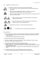
Page 27: ...fire Recommendations 1 Flush the pumps before using them Check with material manufacture for flushing recommendations a When installing new pumps always bleed material from Pump bleeder ports until a...

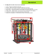
Page 28: ...ntrol Panel User interface to operate control and monitor the Magna Ram 4 Upper Frame Connect the elevator to Follower Plate and contains control valve for pumps 5 Follower Plate Seals the Drum Vents...

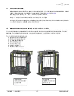
Page 29: ...uilding and troubleshooting refer to the system manual or website sames kremlin com 7 2 Magna Ram Elevator Ram 62 3147 01 RH 62 3147 02 LH The Elevator is used to raise lower the pumps seal the drum a...

Page 30: ...e Bleeder 2 4 62 3009 03 Guide Bushing Assy 19 24 82 5298 02 BHCS M12x1 75x25mm 6 2 62 3035 00 Hold Down Clamp Assy 20 16 82 5298 01 FHCS M12 x 30mm 8 1 65 3224 01 Pneumatic Tubing Assy 21 4 82 5298 0...

Page 31: ...Drum Level Limit Switch 5 1 65 3225 01 Upper Frame Pneumatics 16 4 72 3041 07 Tie Rod Follower 7 1 65 3290 00 Pneumatic Control Panel 22 6 82 3883 02 Plug Tube 2 sq 9 2 62 3065 01 Follower Lock Up Saf...

Page 32: ...th Magnalube 560 440 001 PTFE Grease 6 4 1 2 3 5 Scraper Faces up Dis Assembly 1 Using Snap Ring Pliers remove the Circle Clip 6 2 Using a seal remover Flat Screwdriver pry out the Rod Scraper 5 3 Rem...

Page 33: ...Lubricate 2 Install Piston 5 over Rod 9 3 Loctite 742 SHCS 8 and install Lock Washer 7 and Stop Tube 1 Torque to 125 Lb ft 170Nm 4 Lubricate Wear Strip 2 into Piston 5 groove with PTFE Grease 560 440...

Page 34: ...age and clean old oil Tip When removing piston assemblies oil will drain from the top piston Keep some rags handy Installation 1 Lubricate each Cylinder with 90W oil 2 Lubricate Wear Strip of the Pist...

Page 35: ...qua Control air up Item Qty Part No Description Item Qty Part No Description 1 60ft 85 5595 01 Hose Air in 300 Psi Blue 4 16 30682 8 8B Fitting Swivel 8JICF x 1 2 Barb 2 10 363 001B13 Adaptor 3 8NPTM...

Page 36: ...3 82 5482 00 WASHER FLAT 1 2 531 ID X 1 062 OD 7 3 82 5279 04 NUT LOCK 1 2 13 PLATED 15 1 Y12 8 C NUT HEX 1 2 13 8 3 82 5279 05 SHCS 1 2 13 21 2 LG ASSEMBLY 1 Bolt Side Plates 1 to MagnaRam base using...

Page 37: ...cription 1 1 72 3064 06 Tube Inner Follower Lock Up 8 2 82 0199 11 Washer Flat 3 8 2 1 72 3064 07 Tube Outer Lock Up 1 1 2NPT 9 2 82 0189 12 Washer Lock 3 8 3 1 72 3064 08 Bracket Mount Mid support 10...

Page 38: ...tem Qty Part No Description 28 2 72 3091 00 Label SAMES KREMLIN 5in x 18in Green Text Black 29 1 72 3361 01 Tags Lamacoid MagnaRam Pump Numbers 30 1 72 3361 02 Label MagnaRam Lockout Tagout Informatio...

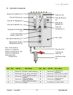
Page 39: ...1 85 5618 08 Indicator Green Pneumatic 12 1 85 5616 08 Valve Selector 2pos 3way 1 4NPTF 61 1 82 3760 40 Air Filter 1 2NPT Empty Drum Indicator 13 Pump 1 Pressure 9 Pump 1 Air Regulator 8 Pump On Pushb...

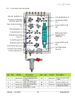
Page 40: ...85 5616 03 Valve 2Pos 5way Dual Pilot 1 4NPT 62 1 85 5618 17 Valve 2Pos 5Way One Pilot Spr Ret 1 4NPT 14 5 85 5616 09 Shuttle Valve 1 4NPT Pump 1 Start Stop 7 Crossover Pump Start One Shot Valve 15 Pu...

Page 41: ...MagnaRam SK 7 6 2 Control Box Top Tube numbers and component descriptions are shown below If using a single stand alone panel Plug Pump Start Crossover Out 21 and Depressurize Stop to Remote 4 5 4 34...

Page 42: ...valves and sends air to both Pump 1 2 pilot regulators a Sends a signal to turn off depressurization valves on single and dual Magna Rams b Both pumps of existing ram turn on and operate at pump air r...

Page 43: ...Version B June 2020 43 MagnaRam SK 7 6 4 Control Box Door Layout...

Page 44: ...Version B June 2020 44 MagnaRam SK 7 6 5 Control Box Subplate Layout...

Page 45: ...Version B June 2020 45 MagnaRam SK 7 6 6 Control Box Back Layout...

Page 46: ...32 82 1100 14 ELBOW 1 4NPTx1 4 OD TUBE PUSH ON 30 2 82 2774 06 ELBOW 1 4 OD TUBE TO 1 4 NPT F 31 2 85 3407 00 ELBOW MALE 1 4IN ODTX1 8IN UNI THREAD 32 19 85 5264 04 TEE UNION 1 4 IN O D TUBE PUSH ON T...

Page 47: ...er 1 8NPT 10 2 365 247 SHCS 6 32 x 1 1 4 4 9ft 668 030 136 Tubing Polyethelene 1 4 OD 11 2 82 0199 39 Washer Flat 6 5 3 82 1100 13 Elbow 1 8NPT x 1 4 Tube 12 2 82 3725 07 Hex Nut Nylock 6 32 6 2 82 52...

Page 48: ...bars Bracket Mounting position Item Qty Part No Description Item Qty Part No Description 1 3 72 3098 04 Bracket Panel Mount 4 8 82 0199 11 Washer 3 8 Flat 2 6 72 3098 03 U Bolt 6 3 16in ID 5 4 82 007...

Page 49: ...8 x 1 5 8 x 1ft 20 2 350 328AQ Elbow St 90 1 NPT 7 5 82 3663 00 Nipple Hex 1NPT 21 1 85 5633 02 Nipple 1 NPT x 3 5 Galv 8 2 365 130 Pilot Regulator Air Valve 1NPT 22 1 85 5633 01 Bushing 1 NPT x NPTF...

Page 50: ...Air Motor Control air is not used Use supplied tubing plugs 7 9 2 Upper Frame Pneumatic Assembly Pump 1 Regulated Air Pump 1 Regulated Air Air Pilot Signal Ports Depressurization Valve Air Supply Air...

Page 51: ...2020 51 MagnaRam SK 7 9 3 Pneumatics Shown assembled to upper frame Mounting Clamps Regulated Air to Pumps Air Motor Control Air supply Depressurization Air Supply Controls Air supply Plant Air Suppl...

Page 52: ...x16JIC 2 2 350 328AQ Elbow St 1 NPT 90 7 8ft 364 982ABL Hose 1in 175 Psi Blue 3 2 85 3470 02 Coupling 1 4 NPTF 8 2 85 5595 05 Elbow 90 1 NPT 4 2 82 3660 00 Nipple Red 1 NPTM x 3 4NPTF 9 2 85 3470 03 N...

Page 53: ...se barb x 16JIC 3 2 82 3660 00 Nipple Hex Red 1 NPTM x 3 4NPTF 8 2 85 5595 05 Elbow 90 1 NPT 4 2 85 3470 02 Coupling 1 NPTF 9 2 85 3470 03 Nipple 1 NPT x 4 Gal 5 4 82 3661 00 Adaptor Hex 16JICMx1 NPT...

Page 54: ...oil 3 Tube O D 15 1 363 001B15 Adaptor 8JIC x NPTM 5 6 85 5212 04 Bulkhead Union ODTube 16 2 30682 8 8B Fitting Barb swivel 8Jic x Barbs 6 4 82 0502 40 SHCS 20 x 1 17 5ft 85 5595 01 Air Hose Blue 300...

Page 55: ...ubing Coils Signals a See wiring schematic for tubing connections 3 Control Air Supply Connection 4 Bracket Tubing Clamp a Bolted to top of Control Cabinet 5 Filter Air Supply Connection 6 1 4 tubing...

Page 56: ...Version B June 2020 56 MagnaRam SK 7 12 3 Utility Brackets Tube Connections Teal Clear Black Teal Clear Black Tubing Coil Color Tubing Coil 1 Tubing Coil 2 Pilot Supply Bracket...

Page 57: ...the up direction The vents prevent a vacuum for occurring that would prevent the ram from raising a Power vents are standard Gravity vents are optional 4 A 3 4 NPT port in the center of the follower a...

Page 58: ...the follower plate 3 Pull the O Ring until it is fully seated in it groove 4 Use the same procedure to install the second O Ring 5 Lubricate the follower rings with compatible grease before inserting...

Page 59: ...tem Qty Part No Description Item Qty Part No Description 1 4 82 0189 43 Washer Lock 10SS 9 1 82 5491 06 Adaptor 3 8 16x 1 2 13 2 4 82 54981 01 SHCS 10 32 x 3 4 SS 10 4 82 5491 07 SHCS 20 x 1 25 SS 3 1...

Page 60: ...ger a Use a soft round tool to push the O Ring into the Plunger Groove 2 Install the Stem 1 and Weight 10 and Lubricate 3 Install the Plunger 7 and tighten the Nut 9 and Lock washer 8 Item Qty Part No...

Page 61: ...e Item Qty Part No Description Item Qty Part No Description 1 1 72 2310 00 Y 1 1 2NPT x 1 1 4NPT SS 10 2 85 5615 02 Adapter Swivel 1 1 4NPTM x 20JICM 2 1 72 3061 01 Bracket Material Plate 11 2 82 3794...

Page 62: ...iption 1 2 85 5595 13 Elbow St 45 1 1 4 NPT 5 2 62 3213 01 Side Port Check Valve 1 1 4 NPT 2 2 85 5595 12 Reducer 1 1 2 NPTM x 1 1 4 NPTF 6 2 080R50 20032060 Hose Rubber 1 14 x2 20MUA x 20MUA 3 2 85 5...

Page 63: ...rt No Description Item Qty Part No Description 1 2 72 2816 02 Nipple 1 BSPTM x 1 1 4NPTF x 4 4 2 300 847 Bleeder Valve 1 4NPT 2 2 62 3213 01 Side Port Check Valve 1 1 4 NPT 5 2 85 5595 13 Elbow St 45...

Page 64: ...1 1 4 NPT 6 2 080R50 20032060 Hose Rubber 1 14 x2 20MUA x 20MUA 2 2 85 5595 12 Reducer 1 1 2 NPTM x 1 1 4 NPTF 7 2 402 763CP 1 4NPT Bleeder Valve Body Plated 3 2 85 5595 11 Adaptor 1 12 BSPPM x 1 1 2...

Page 65: ...o Description 1 2 72 2816 02 Nipple 1 BSPM x 1 1 4NPTF x 4 5 2 402 763CP 1 4NPT Bleeder Valve Body Plated 2 2 62 3213 02 Side Port Check Valve 1 1 4 NPT Plated 6 2 85 5595 13 Elbow St 45 1 1 4NPT 3 2...

Page 66: ...1 1 2 Chrome Ref Inc 300 442RK Repair Kit Side Port Check Valve Apply Loctite 567 to all pipe threads DISASSEMBLY 1 Hold the Cap in a vice 2 Remove the Pipe Plugs from the Body 3 Unscrew the Plug The...

Page 67: ...Ref Inc 62 3213 02RK Repair Kit Side Port Check Valve TC DISASSEMBLY 9 Hold the Cap in a vice 10 Remove the Pipe Plugs from the Body 11 Unscrew the Plug The Spring Ball and O Ring can be removed from...

Page 68: ...Screw 1 2 13x1 5 3 2 72 3238 01 Tie Down Plate 9 24 82 0189 14 Washer Lock 1 2 4 2 82 3725 06 O Ring 4 3 4 x 5 10 4 82 0189 11 Washer Lock 5 16 5 4 82 0259 50 U bolt 2in 11 4 82 0199 10 Washer Flat 5...

Page 69: ...2 0637 83 Hex Screw 1 2 13x1 5 3 2 72 3238 01 Tie Down Plate 9 24 82 0189 14 Washer Lock 1 2 4 2 82 3725 06 O Ring 4 3 4 x 5 10 4 82 0189 11 Washer Lock 5 16 5 4 82 0259 50 U bolt 2in 11 4 82 0199 10...

Page 70: ...e 3 The depressurization valves Opens and redirect the material to under the follower Plate The standard control panel operates the pneumatic depressurization valve The Depressurization kit is used wi...

Page 71: ...ft 668 030 137 Tubing Polyurethane 3 8 10 1 82 1100 13 Elbow 1 8NPT x 1 4ODT Pushlok 4 2 350 623 Reducer HP 1 NPTM x 3 4 NPTF 11 1 080R50 12051212 Hose Rubber 3 4x5 5000Psi 3 4MUA 5 1 362 503AQ Nipple...

Page 72: ...nthly 1 Check the Operation opening and closing and replace if it is not working 2 Replace valve is material is oozing out of the Vent LUBRICANTS and SEALANTS Use Synthetic Grease when rebuilding Note...

Page 73: ...cer 402 925D2 Check Valve Stem 361 900 Socket Shoulder Screw 361 757 3 8 Lock Washer 361 322 6 Lock Washer 361 733 2 O Ring 363 224 Button Cap Screw 361 734 2 O ring 360 012 2 O Ring 361 737 2 Seal 40...

Page 74: ...S 6 and 361 322 6 Lock Washers from the End Cap 402 834 Note There is spring pressure under the cap 2 Remove the End Cap 402 834 from the Housing and Remove its O Ring 361 733 3 Remove the Check Valve...

Page 75: ...and Button Screw 363 733 and tighten 9 Ft Lbs 12 2 Nm 7 Build Seal Cartridge by install the O rings 360 012 and Seals 361 737 on the Seal Spacer 402 842 Note The Shamban Seal Direction Smaller Diamete...

Page 76: ...s Vents Not Shifting Check Air Signals Leaks Operation Ram Raises or Lowers too fast Control Ram air pressures too high Lower Control Ram air pressures Default Raise 60Psi Lower 20Psi Material leaks b...

Page 77: ...ing air motor air lines Check air motor air circuit Limit Valves loose or out of adjustment Tighten and align limit valves Limit Valves or Memory valve defective Replace Limit Memory valve Mac valve n...

Page 78: ...at seal Air Motor not cycling Test Air motor operation Not delivering Material in the Down Stroke Air inside Check Elevator Down Pressure Open bleeder valve on fluid section and cycle pump to remove a...

Page 79: ...435 00 Power Valve 3pos 4way Cyl up down 1 85 5616 10 Vent Timer 2pos 3way 1 363 162 Gauge Back Mount 1 8 NPT 0 160Psi 2 361 679 Empty Drum Limit Roller Valve 1 8 NPT 1 Upper Frame 85 5633 03 Ball Val...

Page 80: ...Version B June 2020 80 MagnaRam SK 10 Control Drawings 45 0538 00 Drawings...

Reviews: