background image


Index revision : A

14

7129

4.3.  Equipment to be connected by the user

WARNING :  The connection of the equipment to the ISOCUBE cabinet by the user must conform 

to standard NF EN 50348.

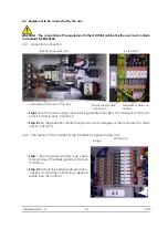
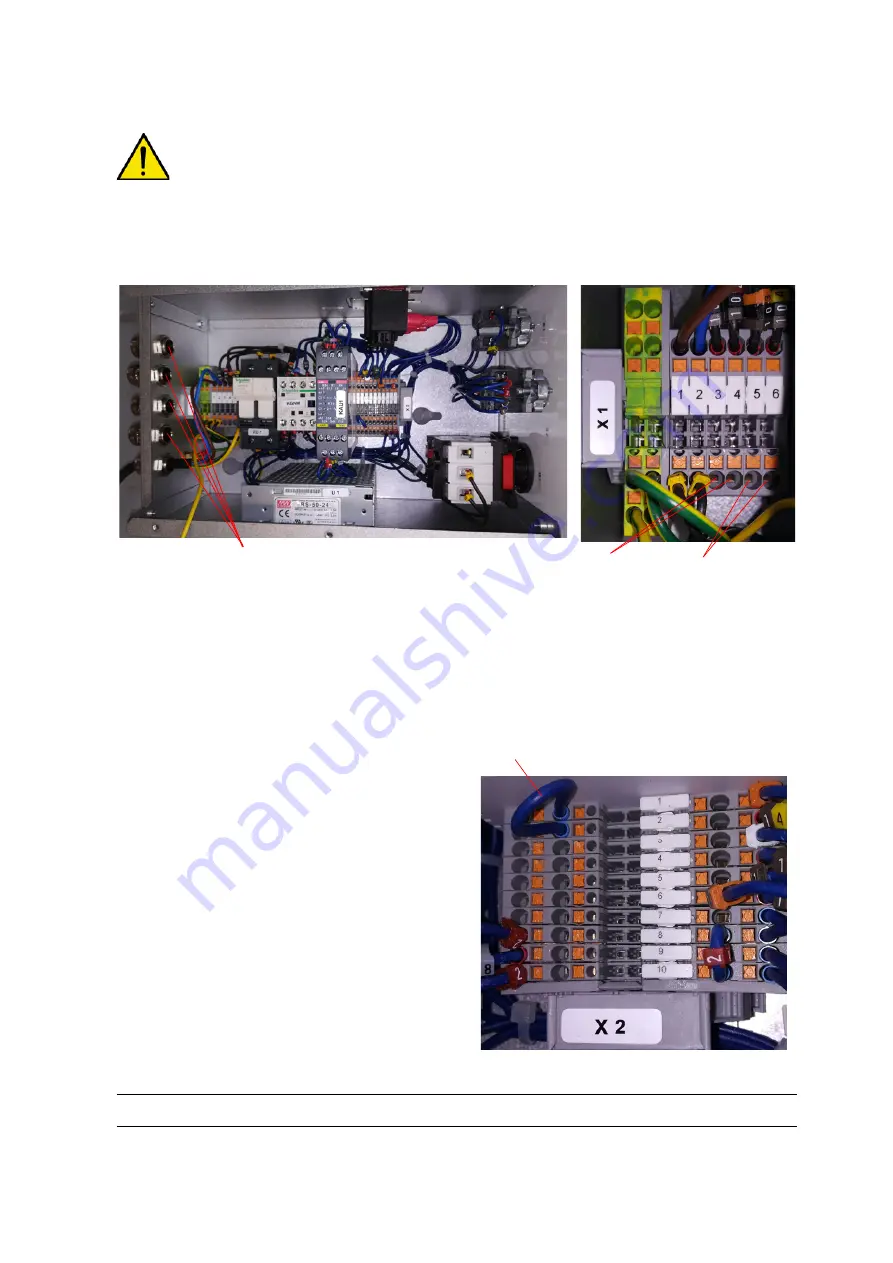
4.3.1.  Generator connection

Step 1:

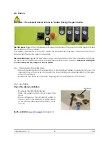
 Run the power supply cable for the generator through a 1st cable gland, then con-

nect it to terminals X1.3 and X1.4


Step 2:

 Run the generator cable through a second cable gland, then connect it to termi-

nals X1.5 and X1.6

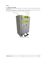
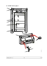
4.3.2.  Connection of the cabinet to the installation's general safety loop

Step

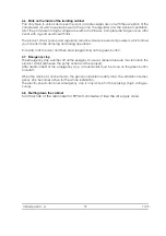
 1: Run the general safety loop cable 

through one of the cable glands at the rear 

of the box.


Step 2:

 Replace the bridge between termi-

nals X2.1 and X2.2 by connecting a general 

safety loop dry contact.


Cable gland at the rear of the box

Electro-pneumatic box

Power supply cable 

connection

Generator cable con-

nection

X1 terminal

X2 terminal

Bridge

Summary of Contents for ISOCUBE

Page 1: ...Index revision A 1 7129 User manual SAMES KREMLIN SAS 13 Chemin de Malacher 38240 MEYLAN FRANCE Tel 33 0 4 76 41 60 60 www sames kremlin com ISOCUBE Isolating cabinet...

Page 2: ...enance of our equipment all year long A catalogue is available on request Select the training programme type of learning method and skills you need from our range to meet your production targets These...

Page 3: ...the cabinet to the installation s general safety loop 14 4 3 3 Connection of a pump 15 4 3 4 Connection of the sprayer s 15 4 3 5 Connection of the product regulator 16 4 3 6 Connection of the high vo...

Page 4: ...ped with systems to prevent this type of risk Potential source of elec tric shock Measures Means applied Voluntary or involuntary contact with the pump or the paint drum Automatic earthing of all part...

Page 5: ...ensure and check that all operators have read and understood the user manuals for peripheral electrical devices present within the spraying perimeter 1 4 Warnings WARNING This equipment may be hazardo...

Page 6: ...ncrete flooring or a metal grating in the spray ing area Never cover the floor with an insulating covering In potentially explosive loca tions the floor assemblies must be antistatic in accordance wit...

Page 7: ...ctrostatic projection equipment according to the instructions contained in this user s manual Only use metal containers to hold the cleaning liquids and connect to ground according to a safe procedure...

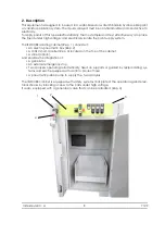
Page 8: ...cabinet Rep 1 consists of An electro pneumatic box Rep 2 A 100kV short circuiter Rep 3 located on the top of the cabinet A stirrer option And enables the integration of A generator An external emerge...

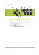
Page 9: ...face Rep Designation 1 Main switch lockable 2 On off button green 3 Air supply pressure 4 Pressure flow regulator 5 Pressure pump power supply 6 Stirring supply pressure 7 Emergency stop 8 Voltage pr...

Page 10: ...to 31 C then linear decrease until 50 relative humidity at 40 C Maximum of 80 without condensation Operating voltage 100 kV maximum Maximum current 500 A max Electrical power supply Voltage Frequency...

Page 11: ...O 8573 1 The values are given for a temperature of 20 C 68 F at atmospheric pressure Characteristics Value Maximum dew point at 6 bar 87 psi Category 4 i e 3 C 37 F Maximum particle size distribution...

Page 12: ...in a case that can be handled using a forklift truck or pallet truck Once out of its packaging the cabinet is handled using the forklift truck or the pallet truck but also using straps through the fo...

Page 13: ...connection the whole time Ensure that the suspension hooks are frequently stripped The elements of the ISOCUBE cabinet electro pneumatic box security systems are delivered connected Connections of the...

Page 14: ...Step 2 Run the generator cable through a second cable gland then connect it to termi nals X1 5 and X1 6 4 3 2 Connection of the cabinet to the installation s general safety loop Step 1 Run the genera...

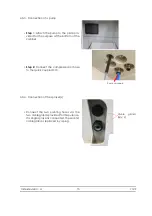
Page 15: ...he bottom of the cabinet Step 2 Connect the compressed air hose to the quick coupler D 10 4 3 4 Connection of the sprayer s Connect the two painting hoses via the two cable glands provided for this pu...

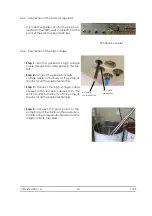
Page 16: ...left Step 2 Connect the generator s high voltage cable to the body of the pump at the link for all the equipotential links Step 3 Connect the high voltage cable present in the Isocube cabinet from the...

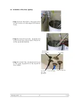
Page 17: ...edge of the recep tacle Step 2 Connect the black equipotential wire to the body of the pump at the link for all the equipotential links Step 3 Connect the compressed air hose to the quick coupler D 8...

Page 18: ...OCUBE is then ready to operate If the door is left open or not locked this second press has no effect 4 5 1 Placement of the paint drum Place the paint drum on the receptacle in the isolating cabinet...

Page 19: ...rinsing operations To restart lock the door and then press single click on the green button 4 7 Emergency stop The emergency stop switches off all the energies However residual pressure may remain in...

Page 20: ...with a multimeter in the ohmmeter position between the earth terminal of the ISOCUBE and the earth terminal of the electrical socket on the power cord The value must not exceed 2 5 1 1 Insulating cab...

Page 21: ...windows of the air pressure indicators may be cleaned with a cloth soaked in water or non aggressive non greasy and non flammable solvent Do not use butyl glycol In this case make sure that the solve...

Page 22: ...ing in the compartment of the tank and the pump Remove the causes of the leak clean and dry the dirty parts Short circuiter defective Check its operation then repair and replace it if neces sary Noise...

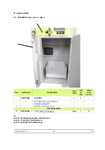
Page 23: ...aintenance Level 2 Corrective maintenance Level 3 Exceptional maintenance Rep Reference Designation Qua ntity Unit of sale Spare parts level 910027658 ISOCUBE 1 1 1 ISOCUBE cabinet equipped see 8 3 pa...

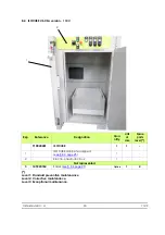
Page 24: ...nce Level 2 Corrective maintenance Level 3 Exceptional maintenance Rep Reference Designation Qua ntity Unit of sale Spare parts level 910028401 ISOCUBE 1 1 1 ISOCUBE cabinet equipped see 8 3 page 25 1...

Page 25: ...Index revision A 25 7129 8 3 ISOCUBE cabinet equipped DES07179 1 2 3 4 5 7 8 11 10 9 6...

Page 26: ...X9SVCB121 C M 4x16 nylon screw containing fibreglass 4 1 1 5 110001738 Alligator clip 20A 1 1 3 6 110002187AT Cable gland 1 1 3 7 910019962 Short circuiter 100 kV see RT Nr 6442 1 1 3 8 110000110AT C...

Page 27: ...u anti ty Unit of sale Level Spare parts 149220760 Fitted stirrer 1 2 1 539280102 Blue polyurethane hose D 6x8 1 m 3 2 049220700 Stirrer see leaflet Ref 573 303 050 1 1 3 3 552486 Female female sleeve...

Reviews: