17
OPERATOR’S MANUAL
SNOW PLOW
RAM
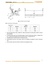
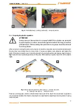
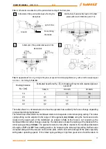
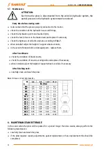
Tab. 4.
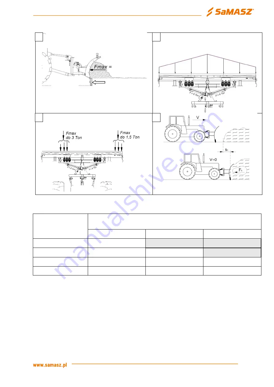
Schematic visualization of the permissible loading of the Ram plow
Tab. 5.
Approximate force
F
h
acting on the plow, at speed
V
and stopping distance
S
h
with a tractor weight equal
to 6 tons
–
Braking distance
S
h
= [cm]
Estimated head force
F
h
= [T], for braking of tractor with mounted plow at
speeds
V
5 km/h
10 km/h
20 km/h
10
1
11
16
20
0,5
3
8
30
0,3
1,2
3
40
0,2
0,5
2
The table above is a demonstration to show the operator how suddenly the forces change depending
on speed and stopping distance.
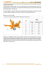
The initial force under which the moldboard starts to tilt depends on the initial spring setting. The initial
spring setting can be adjusted in the range of
0
to approximately
60 mm
using the four tension bolts
located in the upper part of the moldboard. As evident in
this force is not constant as the
moldboard tilts but rather changes unevenly. The table above shows the working of the blade with the
initial spring setting at
30 mm
. The greatest resistance force
Fu
is created in the moldboard between
tilt angles of
55
o
and
65
o
from starting position. By increasing the initial spring setting the
Fu
is also
increased along with the pressure on the entire plow, which can lead to damage of the plow especially
with greater operating speeds. If the initial spring setting is high then great care should be taken to
a)
Schematic of the permissible loads affecting the
Ram plows
uchylająca odkładnicę
Distribution of permissible loads of the Ram
plows with GCJ-63-36x300 up to 6 Ton
Schematic of the permissible loads of the
Ram plows
b)
c)
d)
up to 6 tons
Force tilting
the blade
Ground

