background image


KDT 

REAR DISC MOWER 

OPERATOR’S  MANUAL


3.2.


Design and working principle 

3.2.1.


Rear disk mower 


Fig. 3a. 

Parts of KDT rear disc mower 

 3-point linkage frame 

 Hydraulic cylinder  with support springs 

 V-belt drive 


 Cutterbar  

 Swath discs 

 Safety curtain 


3-point linkage frame (

1)


enables attachment of the mower to tractor’s 3

-point linkage. Drive from 

tractor’s rpm is transmitted through V

-belt drive (

3)

 on the cutterbar (

4

). Hydraulic cylinder (

2)

 is used 

to adjust the mower to working position. It is supplied from outer hydraulics of the tractor. Main frame, 
on which the cutterbar (

4

) is situated, is supported by the springs (

2

). Swath discs (

5)

 are mounted on 

the main frame. 

3.3.


Rear disk mower with tine condioner 


Fig. 3b.

 Parts of KDT rear disc mower with tine conditioner 

 3-point linkage frame 

 Hydraulic cylinder  with support springs 

 Axis gear 

 Cutterbar  

 Swath discs 

 Tine condioner safety curtain 

 Tine conditioner 

 V-belt drive 

 Tine condioner PTO shaft 

10 

 Support legs 

5  6 

10 

Summary of Contents for KDT 220

Page 1: ...64 70 31 fax 48 85 664 70 41 e mail samasz samasz pl www samasz pl OPERATOR S MANUAL Serial No The original operator s manual U S ENGLISH IN221USA011 22 10 2019 EDITION 11 REAR DISC MOWER KDT 180 KDT...

Page 2: ...DISCS HAVE COME TO COMPLETE STANDSTILL DO NOT OPERATE WHEN ANY PERSON REMAINS IN THE DANGER AREA OF 170 ft CAUTION Keep this manual for future reference Well proven design with thousands of machines i...

Page 3: ...for transport 23 5 4 Preparing the mower for transport on public roads 24 5 5 Moving from transport to working position 25 5 5 1 Operating positions of the mower 26 5 6 Preparing the mower for work 2...

Page 4: ...4 Lubrication points 43 8 MALFUNCTION AND THEIR REPAIRS 45 9 DISASSEMBLY AND WITHDRAWAL FROM USE 46 9 1 Disassembly 46 9 2 Scrapping 46 10 WARRANTY CARD 46 11 WARRANTY TERMS 47 11 1 Warranty claims p...

Page 5: ...er operator it should be in working condition and include this operator s manual and all other basic equipment Operator s manual is delivered with every machine so that the operator can familiarize hi...

Page 6: ...wing green fodder such as grass and alfalfa on permanent grassland pastures on crop fields without rocks and forming loose rows of cut forage As a result of the passing of the layers of the green fodd...

Page 7: ...t 1213 lbs 1477 lbs 1599 lbs 1730 lbs 1818 lbs 1818 lbs Cutting speed of the knife 91 m s Disc rpm 3250 rpm Noise level LpA 101 1 dB LAmax 113 1 dB LCpeak 116 1 dB Model KDT 220 S KDT 260 S KDT 260 SL...

Page 8: ...n the cutterbar 4 Hydraulic cylinder 2 is used to adjust the mower to working position It is supplied from outer hydraulics of the tractor Main frame on which the cutterbar 4 is situated is supported...

Page 9: ...drive 9 Roller condioner PTO shaft 10 Support legs 3 point linkage frame 1 enables attachment of the mower to tractor s 3 point linkage Drive from tractor s rpm is transmitted through axis gear 3 on...

Page 10: ...12 4 2 460 7G4N091CE007096MA Tractor mower 21 3 4 4 8 270 8G2N101FX007001 Overload Tine conditioner PTO KDT 260 S SL W 35 2 12 4 2 460 7G4N091CE007096MA Overrunning right Tractor mower 21 3 4 4 8 270...

Page 11: ...plus ear protection and dust mask if necessary During use the machine may give rise to dust especially if the soil is dry You are advised to use a tractor with a cab fitted with filters in the ventila...

Page 12: ...tractor s engine running without supervision Before you leave the tractor turn off the engine and remove the key from tractor s ignition DO NOT operate the mower when driving the tractor backwards Per...

Page 13: ...dangerous unless they are carried out with the utmost caution Have all persons not involved in the actual work move away from the area and limit the zone where the operations are to be carried out Als...

Page 14: ...For mower lifting use only lifting devices with hoisting capacity larger than mower s weight shown in data plate This also applies to ropes and chains used for lifting Do not lift if transport belts...

Page 15: ...cturer with guards in good condition In order to operate safely use only undamaged PTO shafts and shields Damaged PTO shafts and shields must be repaired or replaced with new ones before use Before an...

Page 16: ...rming servicing and machine adjustments with the engine on 4 8 1 Danger of machine entanglement This risk occurs when 1 changing position of a mower 2 operating near rotating parts and 3 working witho...

Page 17: ...ne is operating When the risk of exposure to noise cannot be avoided or eliminated by any protective means or organization of work the employer farmer must 1 provide the operator with individual means...

Page 18: ...son is within the danger area of 170 N 09 CAUTION rotor N 11 Lubrication points N 14 N 15 N 23 Watch out power lines N 16 N 29 N 32 N 35 Cutting height Cutterbar Perfect CUT N 40 N 48 Stay a way from...

Page 19: ...ouch the machine before the rotating parts have not come to a complete standstill N 213 for KDT S SL N 224 Do not open and remove safety guards with motor operating N 52 Hand protection must be worn N...

Page 20: ...r of the mower should have all warning decals provided by the manufacturer 5 OPERATION WARNING Before beginning to use this machine do the following Read manual especially safety precautions in sectio...

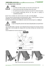
Page 21: ...adjust on the flat ground the mower s position by means of top S and lower W links The cutterbar should lean towards the driving direction Secure the adjustable pin with the bolt R next counter screw...

Page 22: ...kage against falling When the mower is connected the pin should be in the bush 2 on the middle bar Fig 10 1 pin 2 bush 3 hole in the bar G lock 5 2 Mounting PTO shaft PTO shaft s end with overrunning...

Page 23: ...ch the rotating parts because it may lead to serious injuries or even death All service and repair operations must be done only after the tractor engine has been stopped and ignition key off all rotat...

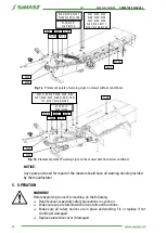
Page 24: ...n the public roads the mower should be equipped with the following devices portable warning light plates to be mounted on both sides of mower top guard in their holders The panel consists of warning p...

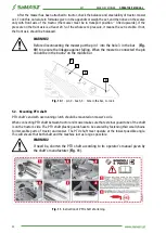
Page 25: ...ck G is released Fig 10 and by means of hydraulic cylinder put the mower into horizontal position with tractor s lever lower the cutterbar to reach the horizontal position in a possibly slow way lower...

Page 26: ...PTO shaft between tractor and mower by means of upper regulating bar of the mower adjust the cutterbar s height and inclination towards the ground Proper inclination of the cutterbar is between 0 and...

Page 27: ...here is however a certain disadvantage creased stubble especially when it comes to lying grass Straight grass may be mowed with horizontal adjustment of the mower and then the stubble will be even but...

Page 28: ...owed at height level 2 4 2 8 but when the grass grows low it should be mowed at 2 The last cut should be mowed a little bit higher 2 8 3 above the ground Too high a PTO rpm whirls the air which may ca...

Page 29: ...ams When operating the mower pay attention to variable conditions on field which may influence the mower clogging and jams such as terrain unevenness height and density of grass as well as other objec...

Page 30: ...otected against falling turn the tractor s engine off and take ignition key off dismount tractor s rpm and place it on a PTO shaft holder that is standard delivered with the mower disconnect hydraulic...

Page 31: ...the warranty When operating check knives for completeness Always check mower before starting work for damaged missing and or worn knives Replace them Fig 20 and Fig 22 if necessary only in sets If the...

Page 32: ...change the knife check disc turns Fig 24 WARNING Different mounting of the knives will block the mower When mounting pay particular attention to loose rotation of the knife on the knife holder pin NO...

Page 33: ...on the 3 point linkage frame of the cutterbar Fig 25 In order to adjust the guide the following should be performed for KDT 180 KDT 220 KDT 260 KDT 300 KDT 340 loosen locknuts 2 and screws 3 shift th...

Page 34: ...220 S KDT 260 S KDT 260 SL loosen eye screw 2 of the swath guide set the swath guide 1 as needed tighten screw 2 even spreading of swath might be adjusted with wheels 3 the same as it is preformed wi...

Page 35: ...ge support chain Support chain is used to ensure 3 point linkage frame of the mower is always at the same height to set the mowing unit parallel to the ground and to relieve the hydraulic lift of the...

Page 36: ...the screw head and spring catch To keep the proper ground pressure of the cutter bar please use the settings provided Fig 30 Fig 30 Ground pressure setting 6 8 Adjusting the space between tine condit...

Page 37: ...ed in pairs opposite featuring the same weight in order to keep shaft well balanced Not keeping the shaft well balanced may lead to premature wearing of bearings as well as the shaft itself Replacemen...

Page 38: ...f fastener There is no torque difference for fine or coarse threads Torque values are based on clean dry threads Reduce value by 10 if threads are oiled before assembly 6 10 Adjusting force of the prs...

Page 39: ...te set must be replaced Fig 34 Spring V belts tensioner 6 11 2 Inspection of tension of toothed belt for gears of rollers and conditioner Drive from cog gear shaft is transmitted on rollers conditione...

Page 40: ...and replace all damaged and or worn parts with new genuine ones clean the mower especially between discs and cutterbar because grass with mud may damage bearings in disc module remove grass and mud a...

Page 41: ...ace may cause the mower to lose stability and turnover NOTICE When stored for long time e g in winter season the machine should be in an upright position on paved surface with closed cylinders Storing...

Page 42: ...ig 37 The oil level can be checked through the check opening B on the side of the gear Please refill the oil until it is visible in the check opening B The oil capacity about 0 26 US gal lqd Tab 7 Oil...

Page 43: ...erbar is on the ground Removing the worked oil from the gearbox is done through the outlet C Tab 8 Oil capacities Fig 38 Roller conditioner s gearbox lubrication points 7 4 Lubrication points Every 50...

Page 44: ...aring lubrication point with LT43 grease in tine conditioner Fig 41 Lubrication point of the suspension with STP grease Fig 42 Lubrication point of the suspension with STP grease Lubrication point Lub...

Page 45: ...clination towards the front 4 cm Grass blocks the mower lack of grass flow or the flow is uneven Too low work speed Speed up to 10 km h or more Swath guides are set too narrow Widen swath guides to th...

Page 46: ...it should be withdrawn from use For this purpose oil from intersecting axis gear and cutterbar should be drained and delivered to a proper waste treatment company Clean the mower parts dismantle and...

Page 47: ...stacle e too fast lowering of the cutterbar to the ground f transport and accidental damage g breaking damage of tine conditioner s shaft 6 The Purchaser bears the costs of technical estimation when t...

Page 48: ...ps pointed by the dealer The dealer is obliged to indicate them NOTICE The Manufacturer have right to introduce design modifications NOTICE The SaMASZ company constantly works on development of all of...

Page 49: ...on unloaded tractor MP kg Total weight of machine mounted on front 3 point linkage or weight of front ballast MT kg Total weight of machine mounted on rear 3 point linkage or weight of rear ballast A...

Page 50: ...r s rear axis TT rzecz Tyre load capacity apply double the load indicated by the tyres manufacturer Enter the above calculation data and technical data provided by the manufacturer in the below table...

Page 51: ...51 OPERATOR S MANUAL REAR DISC MOWER KDT...

Page 52: ...52 KDT REAR DISC MOWER OPERATOR S MANUAL SaMASZ Sp z o o ul Trawiasta 1 16 060 Zab ud w Polska tel 48 85 664 70 31 fax 48 85 664 70 41 e mail samasz samasz pl www samasz pl...

Reviews: