Version: EN-UM-1.0
USER MANUAL
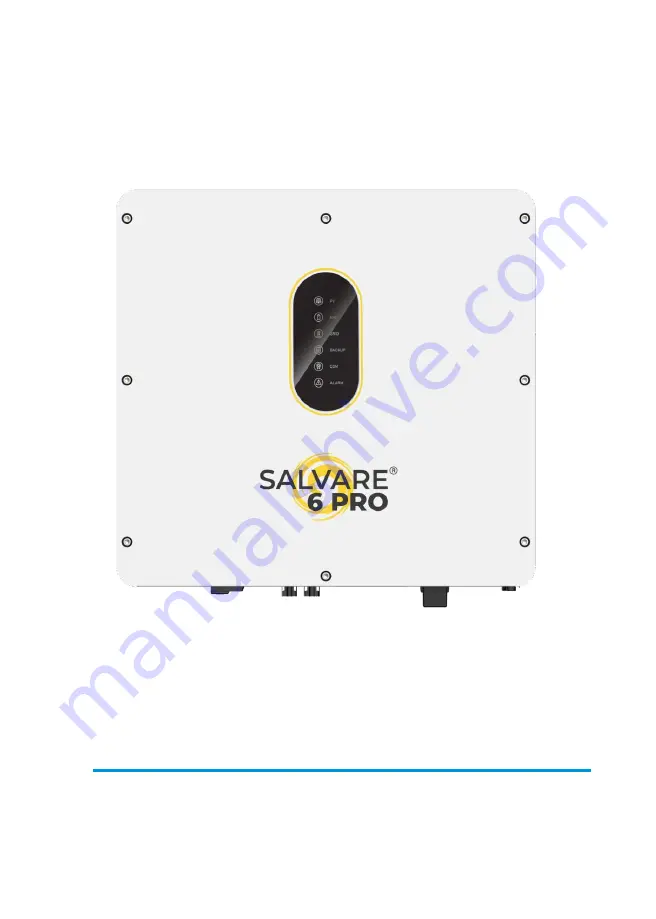
SALVARE 6 PRO Single-phase ESS Inverter
Page 1: ...Version EN UM 1 0 USER MANUAL SALVARE 6 PRO Single phase ESS Inverter...
Page 2: ...HISTORY VERSION ISSUED COMMENTS V1 0 31 Jul 23...
Page 3: ...applicable to the following inverters SALVARE 6 PRO Conventions The following safety instructions and general information are used within this user manual DANGER Indicates an imminently hazardous situ...
Page 4: ...ecaution 2 Product Introduction 2 1 Overview 2 2 Product Appearance 2 3 Model Definition 3 Installation 3 1 Packing List 3 2 Selecting the Mounting Location 3 3 Mounting 4 Electrical Connection 4 1 Gr...
Page 5: ...ng Mode 5 2 Startup Shutdown Procedure 6 Commissioning 6 1 Inspection 6 2 Commissioning Procedure 7 User Interface 7 1 LED 7 2 App Setting Guide 8 Maintenance 8 1 Routine Maintenance 8 2 Inverter Trou...
Page 6: ...perator or a third party and damage to the inverter and other properties belonging to the operator or a third party 1 1 Symbols Used Safety Symbol Description Danger of high voltage Only qualified per...
Page 7: ...ter otherwise the inverter may be damaged and the warranty annulled When exposed to sunlight the PV array generates dangerous high DC voltage Please operate according to our instructions or it will re...
Page 8: ...Typically an ESS inverter system consists of PV array ESS inverter battery loads and electricity sensor The energy generated by inverter can be preferentially supplied to its self consumption stored i...
Page 9: ...Product Introduction ESS Inverter User Manual 9 2 2 Product Appearance 515mm 175mm External Switch The External View of the Inverter 487mm 555 6mm...
Page 10: ...175 8 1 2 3 4 5 6 7 9 The Bottom View of the Inverter 1 Battery Input Terminals 2 PV Switch 3 PV Input Terminals 4 COM1 Ports USB PARAL RS485 DRM CT METER BMS NTC RMO DRY 5 COM2 Port GPRS WIFI LAN 6...
Page 11: ...Introduction ESS Inverter User Manual 11 5KHB 60 Charge discharge current 60A Hybrid Power 5000W 2 3 Model Definition The letters in the product model have the specific informations Take 5KHB 60 as an...
Page 12: ...erter B 1 Mounting bracket C 1 File package D 2 2 PV terminal connector group PV PV N A for AC Couple E 2 BACKUP GEN connector F 1 GRID connector G 2 Battery connector H 1 Meter Optional I 1 CT J 3 M1...
Page 13: ...fe the ambient temperature must be below 50 e The inverter must be mounted in a well ventilated environment to ensure good heat dissipation f To ensure long service life the inverter must not be expos...
Page 14: ...ly or tilted backward by max 15 The device can not be installed with a wrong mode and the connection area must point downward 3 2 3 Installation Space Requirements To ensure the inverter normally and...
Page 15: ...screw kit into the hole together with a hammer Refer to Figure c Note Do not remove the nut unit in this step 3 After tightening 2 3 buckles the expansion bolts are tight and not loose and then unscre...
Page 16: ...diagram Non parallel connection mode CT Meter communication connection BMS communication connection GEN DRY communication connection Note 1 PV related contents are N A for AC Couple inverter 2 BMS con...
Page 17: ...id Inverter Pin Function USB PARAL RS485 Turn this switch to ON G GND_S S PARA_SYNC L CAN_L H CAN_H DRM CT METER BMS Normal Load Critical Load L N Parallel communication connection CT Meter communicat...
Page 18: ...S communication connection is only for lithium battery 3 It is necessary to turn the matched resistance switch of No 1 inverter and No N inverter to ON in parallel connection mode 4 With parallel conn...
Page 19: ...itical Load Pin Function USB PARAL RS485 Normal Load G GND_S S PARA_SYNC L CAN_L H CAN_H DRM CT METER BMS DDSU666 1 5 6 A 9 10 24 25 Flow from grid to inverter Parallel communication connection CT Met...
Page 20: ...ry to additionally purchase suitable CT and meter according to the specific requirements in parallel connection mode Scheme B 4 It is necessary to turn the matched resistance switch of No 1 inverter a...
Page 21: ...ive earth PE terminal is equipped at the side of the inverter Please be sure to connect this PE terminal to the PE bar for reliable grounding AWG 10 or 12 yellow green lines are recommended If the pos...
Page 22: ...is recommended to use outdoor dedicated cables with multiple copper cores A B C Tighten three screws and ensure each screw 1 cap does not exceed the surface Earth Click A Diameter 14 20 10 14 10 14mm...
Page 23: ...battery This ensure the inverter can be security disconnected during maintenance A B C A Diameter 10 12mm B Cross Section 25mm C Strip Length 10mm a b c Hydraulic Pressure Crimper DC Breaker 150A It...
Page 24: ...Electrical Connection 24 ESS Inverter User Manual NTC connection for lead acid battery Pin8 9 Pin Function Pin8 GND_S Pin9 NTC BAT Temperature sensor...
Page 25: ...unding conductor The minimum insulation resistance to ground of the PV panels must exceed 18 33k there is a risk of shock hazard if the requirement of minimum resistance is not met NOTICE Electrical C...
Page 26: ...efault The meter is optional N Inverter Side L N Grid Side L DDSU666 5 80 A Before connecting to Grid please install a separate AC breaker not equipped between meter and Grid This ensures the inverter...
Page 27: ...2 CT Connection Before connecting to Grid please install a separate AC breaker not equipped between CT and Grid This will ensure the inverter can be safely disconnected during maintenance The connecti...
Page 28: ...for parallel communication A matched resistance switch for parallel communication RS485 4 Pin interface for RS485 communication DRM Demand response mode for Australia application CT METER For Meter co...
Page 29: ...into corresponding port 2 Screw the waterproof cover back to inverter firmly with 4 x M4 screws 1 2N m c 3 Install the seal into the threaded sleeve fasten the rubber nut Make the RJ45 terminal accord...
Page 30: ...n waterproof cover 2 1 3 1 Insert RJ45 terminal into corresponding port 2 Screw the waterproof cover back to inverter firmly with 4 x M4 screws 1 2N m c 3 Install the seal into the threaded sleeve fas...
Page 31: ...al Configuration of Meter CT Communication Pin 12345678 PIN 1 2 3 4 5 6 7 8 Function Description RS485_A RS485_B RS485_A RS485_B CT CT NC NC 4 6 3 1 Meter Connection Meter cable connection overview In...
Page 32: ...side Rubber nut Seal Waterproof cover Press the meter cable in the seal via the side incisions Make the RJ45 terminal according to above function description of each Pin definition 3 Install the seal...
Page 33: ...ons Make the RJ45 terminal according to above function description of each Pin definition 3 Install the seal into the threaded sleeve fasten the rubber nut c waterproof cover 1 Insert RJ45 terminal in...
Page 34: ...o corresponding port 2 Screw the waterproof cover back to inverter firmly with 4 x M4 screws 1 2N m 3 Install the seal into the threaded sleeve fasten the rubber nut Make the 4 Pin terminal according...
Page 35: ...communication cable connection overview No 1 Inverter No 2 Inverter No N Inverter It is necessary to turn the matched resistance switch of No 1 inverter and No N inverter to ON in parallel connection...
Page 36: ...2N m 3 Install the seal into the threaded sleeve fasten the rubber nut Make the 4 Pin terminal according to above function description of each Pin definition Lead the RS485 cable through the rubber n...
Page 37: ...9 Pin terminal NTC RMO DRY Control Module s Rubber nut Inverter side Seal Waterproof cover Press the NTC RMO DRY cable s in the seal via the side incisions Unscrew the waterproof cover and loosen the...
Page 38: ...cover back c to inverter firmly with 4 x M4 screws 1 2N m 4 6 7 GPRS WIFI LAN Module Connection Optional For details please refer to the corresponding Module Installation Guide in the packing The appe...
Page 39: ...xcess energy is used to charge the battery and the remaining energy is fed into the grid This is the default mode to increase self consumption rate There are several situations of self used working mo...
Page 40: ...the demand is not met the loads will consume grid energy 5 1 2 Feed in Priority Mode Go to the Hybrid work mode menu and select the Feed in priority mode Under this mode the priority of PV energy cons...
Page 41: ...PV energy is wealthy the PV energy will be first consumed by loads If there is excess PV power the power will be fed into grid If there is still PV energy left after load consuming and grid feeding th...
Page 42: ...oad P BAT P Load BACKUP BACKUP c No PV Input The inverter will first discharge the battery energy for home load consuming when no PV input such as in the evening or some cloudy or rainy days If the de...
Page 43: ...charging the battery quickly and at the same time you can choose whether to allow AC to charge the battery Forbid AC charging In this mode the battery can be charged only with PV power and the chargi...
Page 44: ...he battery can be charged both with PV and AC a Wealthy PV power When PV energy is wealthy PV charges the battery first then meets the loads and the rest is fed into the grid b Limited PV power When t...
Page 45: ...he system automatically switches to Off Grid mode Under off grid mode only critical loads are supplied to ensure that important loads continue to work without power failure Under this mode the inverte...
Page 46: ...battery capacity larger than 100Ah to ensure BACKUP function work normally If BACKUP output loads are inductive or capacitive loads to make sure the stability and reliability of system it is recommend...
Page 47: ...r on the Battery 3 Power on the AC 4 Power on the BACKUP 5 Connect the cell phone App via Bluetooth Please refer to Section 7 2 for details 6 Click the Power ON in the App for the first time Please re...
Page 48: ...following the contents and notifications of this manual and there are enough spaces for operation maintenance and ventilation 2 All the terminals and cables are in good status without any damages 3 No...
Page 49: ...PV input is normal Blink PV input is abnormal Off PV is unavailable BAT On Battery is charging Blink Battery is discharging Battery is abnormal Off Battery is unavailable GRID On GRID is available an...
Page 50: ...er load DC EPS output voltage abnormal D7 EPS over dc bias voltage CP Details Details Code PV Grid BAT BACKUP COM LED LED LED LED LED ALARM LED PV normal No PV PV over voltage B0 PV under voltage B4 P...
Page 51: ...abnormal CF Boost abnormal CG Dc dc abnormal CU Details Code PV LED Grid LED BAT LED BACKUP COM ALARM LED LED LED RS485 DB9 BLE USB Inverter over temperature C5 Fan abnormal C8 Inverter in power limit...
Page 52: ...u need to grant all access rights in all pop up windows when installing the APP or setting your phone 7 2 2 App Architecture It contains Cloud Login and Local Connection Cloud login APP read data from...
Page 53: ...ll access rights in all pop up windows when installing the APP or setting your phone When the APP asks for permission please click Allow Connect Inverter Firstly open the Bluetooth on your own phone t...
Page 54: ...Skip this step if the communication mode of the inverter is GPRS 2 Our device only supports 2 4G wifi If your signal is 5G wifi please switch 3 If you need help with network configuration please clic...
Page 55: ...2 Click Previous back to the previous page 1 2 3 4 5 Step3 Set parameters for the inverter to connect to the power limit Power control Click each item to enter the informations Next Previous Maximum f...
Page 56: ...messages The icon and color definition as below Color Blue Definition Load consumption only from PV Color Red Definition Battery charge power with PV or AC Color Red Definition Battery discharge powe...
Page 57: ...Load power curve Query Daily Data Go to Chart Day page It will show the Daily Production or Consumption Curve in this page You can swipe the screen left and right to switch the graph Day Chart Product...
Page 58: ...ick Setup Chart Home Log Console XXXXXXXX PV power curve Day Chart Consumption The above combination day chart shows the load consumption power from three parts PV generation power Blue battery discha...
Page 59: ...capacity Query Monthly Data Go to Chart Month page It will show the Monthly Production or Consumption Curve in this page You can swipe the screen left and right to switch the graph Day Chart Producti...
Page 60: ...Load consumption capacity from PV Load consumption capacity from battery Load consumption capacity from grid Month Chart Consumption The above combination month chart shows the load consumption capac...
Page 61: ...Query Yearly Data Go to Chart Year page It will show the Annually Production or Consumption Curve in this page You can swipe the screen left and right to switch the graph Year Chart Production The ab...
Page 62: ...Setup Chart Home Log Console XXXXXXXX Load consumption capacity from PV Load consumption capacity from battery Year Chart Consumption The above combination year chart shows the load consumption capaci...
Page 63: ...Home i Log Console 494kWh E Total XXXXXXXX 19 1kWh E Today 494kWh E Total XXXXXXXX 19 1kWh E Today 24 0 76 0 24 0 76 0 47 0 53 0 The alarm list CC Software incompatibility Home This page shows the bas...
Page 64: ...h PV Supply directly 7 50kWh Basic Current Power From Grid 2 37kWh 2 71kW Quick Setup Chart Home i Log Console 494kWh E Total XXXXXXXX 19 1kWh E Today 24 0 76 0 47 0 53 0 Console This page shows Maint...
Page 65: ...ly 10 1kWh To Grid 8 97kWh Consumption 9 87kWh PV Supply directly 7 50kWh Basic Current Power From Grid 2 37kWh 2 71kW Quick Setup Chart Home i Log Console Then you need to enter password in a popup w...
Page 66: ...User Interface 66 ESS Inverter User Manual In this page you can view the basic information like some version information do some maintaining operations like turn off on the inverter and manage data...
Page 67: ...User Interface ESS Inverter User Manual 67 Access Management Go to Console Access Management page In this page you can switch the login permission...
Page 68: ...68 ESS Inverter User Manual Communication Setting Go to Console Communication Setting page In this page you can set or change the parameters of communication settings Basic Setting RS485 Setting and E...
Page 69: ...ange the parameters of Grid side as shown in the figure Feature Parameters Go to Console Feature Parameters page In this page you can set or change the feature parameters as shown in the figure Power...
Page 70: ...e and enter the Autotest page to click START Step 3 Then the inverter is autotesting Wait for about 10 minutes the autotest process will be finished Step 4 You can click the DOWNLOAD to save the data...
Page 71: ...User Interface ESS Inverter User Manual 71 XXXXXXXX...
Page 72: ...In this page you can set or change the Reactive Power Control parameters Other Setting Go to Console Other Setting page In this page you can set other setting parameters Enable Buzzer On to open the B...
Page 73: ...User Interface ESS Inverter User Manual 73 XXXXXXXX Hybrid Setting Go to Console Hybrid Setting page In this page you can set Hybrid Setting parameters...
Page 74: ...her to allow the grid to charge the battery which is prohibited by default If the user enables the Grid charge function the parameter of Maximum grid charge power and Bat Voltage of grid charge end ca...
Page 75: ...id Setting page you can also find Time based Control function This function is designed to control the time setting of charging and discharging the inverter You can set the following parameters based...
Page 76: ...ting value W Maximum GEN charger power W Maximum battery charge power from generato Generator start SOC Battery SOC below which the generator starts to charge the battery Meanwhile the generator runni...
Page 77: ...the GEN Port function will be enabled and the Generator Input will be ON When the Battery SOC 100 or the Runtime is over Generator Max Runtime Min the GEN Port function will be disabled and the Gener...
Page 78: ...ing value Power simultaneously and then the Smart Load will switch on Battery SOC of Smart Load Off Battery SOC below which the Smart Load will switch off Always On with Grid When click Always On with...
Page 79: ...hybrid inverter works under off grid mode As the battery SOC reaches gradually to the setting value Off during the process the grid tied inverter output power will decrease linear When the battery SO...
Page 80: ...d Off art Load ON 500W Smart Load Off Battery SOC 100 Smart Load ON Smart Load Off Runtime Generator Max Runtime Off Grid 80 Gen Dry contact start Generator Input On Runtime Generator Generator Input...
Page 81: ...rter cleaning Check periodically that the heat sink is free from dust and blockage Clean periodically the heat sink Yearly Inverter running status Check that the inverter is not damaged or deformed Ch...
Page 82: ...her than the standard voltage modify the number of pv module connection strings B1 PV insulation abnormal 1 Check the insulation resistance against the ground for the PV strings If a short circuit has...
Page 83: ...er service center C5 Inverter over temperature 1 If the alarm occurs occasionally the inverter can be automatically restored no action required 2 If the alarm occurs repeatedly pls check the installat...
Page 84: ...rs repeatedly the inverter cannot work properly Pls contact the customer service center CG Boost abnormal 1 If the alarm occurs occasionally the inverter can be automatically recovered and no action i...
Page 85: ...battery is abnormal 5 If exclude the above the alarm continues to occur please contact the customer service center D5 Battery over temperature 1 If the alarm occurs repeatedly please check whether the...
Page 86: ...side is open circuit ground to ground etc If exclude the above the alarm continues to occur please contact the customer service center CP BACKUP over dc bias voltage 1 If the alarm occurs occasionall...
Page 87: ...ition indicated in the drawing press inward and then take out the connector outward PV Connectors Removing Detail Grid BACKUP GEN Connectors Removing Detail 8 3 Removing the Inverter Perform the follo...
Page 88: ...20 20 N A Startup voltage V 90 90 N A MPPT voltage range full load V 280 480 200 480 200 480 200 480 200 480 230 480 230 480 N A No of MPPT trackers 2 2 N A String per MPPT tracker 1 1 N A Input BAT...
Page 89: ...tage V 230 230 Nominal output frequency Hz 50 60 50 60 Transfer time ms 10 type 20 max 10 type 20 max THDV 3 100 R load 3 100 R load Nominal output power W 3000 3000 4600 3000 5000 3000 6000 4600 5000...
Page 90: ...rent protection Support Support AC overvoltage category III III PV overvoltage category II N A Surge Arrester DC Type III AC Type III AC Type III PV switch Support N A Anti islanding protection Suppor...
Page 91: ...Dedicated AC connector Display Communication Display LED APP LED APP Communication interface Certification Grid BMS CAN RS485 LAN WIFI GPRS DRMs Meter RS485 USB IEC61727 VDE AR N4105 IEC62116 CEI0 21...