


18
Fig. 12.4 Connection of temperature sensors
Temperature sensors are equipped with
brass coat with diameter of 6mm and 50mm
long. They should be installed possibly close to
the temperature measurement point. The sensors
must be installed so that the brass coat is
thermally insulated from the environment.
The collector temperature sensor must be
located in the collector tube possibly deep, as
this is conditional for correct measurement.
The reservoir temperature sensor must be
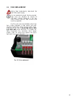
located in thermometric tube between the supply
and return connectors of the collector exchanger
pipe coil.
The sensors resistance per temperature
table:
CT6w\CT6
Temp.
°C
Min.
Ω
Nom.
Ω
Max.
Ω
0
999,7
1000,0
1000,3
25
1096,92
1097,35
1097,77
50
1193,42
1193,97
1194,52
100
1384,26
1385,06
1385,86
125*
1478,59
1479,51
1480,44
150*
1572,2
1573,25
1574,30
*only for CT6w sensor
13.
HOW TO CLOSE CASING
To close the unit casing hook the casing cover
with recesses against the base insets (shown in
Fig. 13.1)
Fig. 13.1 Casing closing first step
Then, press the cover in place indicated
by red arrow (Fig. 13.2), until you clearly hear
the latch click.
Fig. 13.2 Casing closing second step
Summary of Contents for PCSol 150
Page 2: ......
Page 6: ...6...
Page 7: ...OPERATING MANUAL PCSol 150...
Page 13: ...INSTALLATION MANUAL PCSol 150...
Page 22: ......
Page 23: ......
Page 24: ...SALUS Controls Made in Poland...


