


21
Hydraulic scheme no. 3 -
diagram “A” with heat buffer
3
:
1
–
boiler with integrated pump
2
–
pump
3
–
temperature sensor
4
–
heat buffer
5
–
fireplace pump controlled by fireplace regulator
6
–
temperature sensor
7
–
fireplace with water jacket
8
–
regulated circuit water temperature sensor (H2)
9
–
circuit pump (H2)
10
–
electrical servo of H2 regulated heat circuit
11
–
fireplace regulator
12
–
plate heat exchanger
13
–
thermostatic valve protecting return temperature
14
–
solar pump
15
–
solar panel
16 - solar collector temperature sensor
17
–
temperature sensor of water for loading the buffer
with a solar pump
18
–
lower solar temperature sensor
19
–
DHW circulation pump.
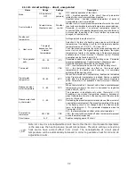
PROPOSED SETTINGS:
Parameter
Setting
MENU
Hydraulic diagram
3
menu
→
service settings
→
System
Selection
ON
menu
→
service settings
→
System
→
Additional heat source
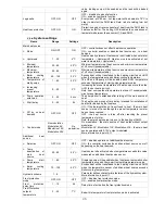
Temperature deactivating main
heat source
35
C
menu
→
service settings
→
System
→
Additional heat source
Cooling temperature
92
C
menu
→
service settings
→
System
→
Additional heat source
Minimum temperature
25
C
menu
→
service settings
→
System
→
Additional heat source
Maximum DHW temperature
80
C
menu
→
service settings
→
Solar
DHW priority
OFF
menu
→
service settings
→
HUW settings
Description: Pump (2) works together with boiler (1). When boiler (1) switches off, pump (2) deactivates with 5 minute
delay. After fireplace sensor (6) is heated up to a temperature of (35
C), boiler (1) and pump (2) deactivates with 5
minute delay. Pump (5) is controlled by fireplace regulator (11). When (6) exceeds 92
C, heat excess will be transferred
to heat and HUW circuits. Pump (9) will switch off if temperature on sensor (3) drops below 25
C. Pump (14) switches
off after exceeding 80
C.
3
Shown hydraulic diagram does not replace a central heating system and can be used only for demonstrative purposes
!