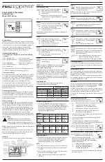
Dimensions
A - 75 mm
B - 75 mm
C - 30.5 mm
A
B
A
Salus Controls plc
Enterprise Park, Bala Gwynedd, LL23 7NL
Regional offices,
England & Scotland.
Web: www.salus-tech.com Email: [email protected]
Sales:
+44 (0) 8700 766900
Technical:
+44 (0) 8700 766902
Email:
Maintaining a policy of continual product development Salus Controls plc. reserve the right to change
specification, design and materials of products listed in this brochure without prior notice.
Manual Issue No. IM-ERT30-001
Important:
The thermostat must be disconnected from its power supply before its housing is opened.
Wall mounting
The housing cover must be separated from the base plate before the controller is fitted.
Follow the steps listed below:
1. Loosen the screw on the underside.
2. Open the housing by removing and then lifting off the housing lid on the underside.
3. Now fix the base plate with the screws supplied on the wall or on the flush mounting box.
Factory setting
-
Display of actual temperature in
°
C
-
Normal operation (not lowered)
-
Desired temperature 20
°
C
Basic settings
The jumpers on the PCB can be used to turn on or off various functions of the ERT 30:
The factory setting for all these functions is ON. You can change these settings according
to your own requirements by moving the contact terminals on the jumpers.
Important:
The contact terminals should not be removed!
As long as the installation is carried out to a professional standard, the criteria for protection
class II will be satisfied.
ERT 30 symbol
Meaning
Temperature lowering active
Heat requested
blinkend
Frost protection mode active
Cooling operation active
Wiring diagram
The thermostat must be wired in accordance with the wiring diagram
below:
ERT 30
230 V Model
Terminal
Lead for temperature reduction
(timer)
N
Neutral conductor supply lead
L
230 V power supply lead
Switch output (valve actuator,
terminal strip)
ERT 30
24 V Version
Terminal
L2
24 V power supply
NC
Circuit closed once temperature
1
Centre-point connection
NO
Circuit open once temperature
reached
2
L1
24 V power supply
1
e.g. cooling unit
2
e.g. heating unit
Technical data
230 V
24 V
Product no.:
surface mounted
flush mounted
112.300
112.306
112.301
-
Operating voltage:
230V AC / 50Hz
24V AC / 50 Hz
Electronic switch output
Max. switching current:
10 (3) A
Max. no. of
valve actuators:
5 Stück · 3W
Hysteresis
0,5K
Protection class:
IP 30
Dimensions W/H/D:
75 mm / 75 mm / 30,5 mm
Temperature range:
5
o
C - 30
o
C
Storage temperature:
-25
o
C - 65
o
C
Explanation of symbols
ERT 30 Jumpers
Switch
Function
ON
OFF
VP
Valve protection
function
PWM
Pulse width modulation
Temperature reduction
Digital Room Thermostat
for under floor Heating Model No:- ERT30


