background image

ITALIANO

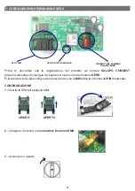
5. CONFIGURAZIONE ESPANSIONE GPRS

7

6 - 

Attivare la connessione dati inviando un 

SMS

 alla 

SIM

 installata

<apn<apnoperatore>

  (es. 

<apn<wap.tim.it>

).

sull’espansione 

GPRS

 con l’

APN

 del proprio operatore telefonico 

con la seguente dicitura:

7 - 

Attendere la conferma dell’avvenuta configurazione dell’

APN


tramite la ricezione di un 

SMS

 con la dicitura:  

APN OK

8 - 

Il 

LED

 comincerà ad emettere un lampeggio ogni 300ms.

SMART CONTROL PLUS

SMART CONTROL PLUS

4 - 

Attendere che il modulo 

GPRS

 dia avvio alla ricerca del segnale. Il 

LED DI STATO SEGNALE

emetterà


un lampeggio ogni 800ms.

5 - 

Attendere che il modulo 

GPRS

 si sia agganciato alla rete 

GSM

. Il 

LED DI STATO SEGNALE 

emetterà


un lampeggio ogni 3 secondi.

9 - 

Non appena verrà assegnata la matricola all’espansione, verrà visualizzata solo per una volta il 

numero di matricola sul display.

VIENE ASSEGNATA

LA MATRICOLA

ALL’ESPANSIONE. 

SERIAL   NUMBER

x x x x x x

400 V                                        13.2A

Cf    0.80                                    0 h

QUESTA SCHERMATA VISUALIZZA

LA MATRICOLA DELL’IMPIANTO,

SARÀ PRESENTE SOLO ALLA

PRIMA CONFIGURAZIONE

DELL’ESPANSIONE. 

1 - 

Inviare un 

SMS

 con la dicitura 

<serial>.

È anche possibile richiedere la matricola da remoto:

2 - 

Attendere la risposta da parte del dispositivo tramite 

SMS

 con 

la dicitura 

Serial: 

XXXXXX


SALUPO CONNECT

SALUPO CONNECT

Summary of Contents for SMART CONTROL PLUS

Page 1: ...IONE E INSTALLAZIONE INSTRUCTION AND INSTALLATION MANUAL Dispositivo per telecontrollo GPRS con display Device for GPRS remote control with display SMART CONTROL PLUS MADE IN ITALY SC100 29 xx rev 1 2...

Page 2: ...29 xx 4 4 Piattaforma Salupo Connect 5 5 Configurazione espansione GPRS 6 6 Registrazione su Salupo Connect 8 7 Programmazione su Salupo Connect 9 8 Monitoraggio su Salupo Connect 12 9 Schermate setu...

Page 3: ...ni evitando di danneggiare i morsetti metallici e le relative sedi Prima di qualsiasi operazione da effettuare all interno escludere l alimentazione generale 1 ISTRUZIONI GENERALI PER L INSTALLAZIONE...

Page 4: ...100 29 230 24 Vdc SC100 29 24 L1 N 1 2 5 6 9 10 1 2 C C C C DIGITAL INPUT NC NC NC NC NO NO NO NO COM OUT 1 OUT 2 OUT 3 OUT 4 24Vdc 230Vac COM COM COM L1 N DIGITAL INPUT DIGITAL INPUT INPUT 4 20mA 3 4...

Page 5: ...ezionare la lingua tra Italiano Inglese Francese e Spagnolo Personalizzazione del profilo permette l accesso a clienti ed installatori con profili dedicati e mail in caso di allarme Questo permette l...

Page 6: ...ortale SALUPO CONNECT https www salupo it bisogna configurare in modo corretto il modulo GPRS Prima di dare inizio alla configurazione assicurarsi che la SIM abbia la richiesta del PIN disattivata 2 C...

Page 7: ...TATO SEGNALE emetter un lampeggio ogni 800ms 5 Attendere che il modulo GPRS si sia agganciato alla rete GSM Il LED DI STATO SEGNALE emetter un lampeggio ogni 3 secondi 9 Non appena verr assegnata la m...

Page 8: ...la registrazione compilando tutti i campi richiesti e inserendo la matricola pervenuta in precedenza Una volta effettuata la registrazione l account sar creato e verr inviato un link di attivazione a...

Page 9: ...to Online Offline il relativo funzionamento Regolare Allarme e pu aggiungere altri impianti non ancora registrati Cliccando sull impianto desiderato si accede nella sezione Monitoraggio Inserendo le p...

Page 10: ...pop up il quale richiede la conferma per dissociare l utente corrente dall impianto 3 Per collegare un nuovo utente basta cliccare sul pulsante e si verr reindirizzati sulla pagina Scheda utente Da q...

Page 11: ...bilire il range del sensore installato e selezionare l unit di misura pi appropriata impostare l attivazione della soglia ON OFF e associarlo ad un uscita digitale 2 Programmare gli ingressi analogici...

Page 12: ...eleziona icona 8 MONITORAGGIO SU SALUPO CONNECT Da qu possibile accedere nella sezione Monitoraggio cliccando sull apposito pulsante Monitoraggio Dettagli impianto Setup quadro Storico La sezione Moni...

Page 13: ...L V 1 0 LO STATO DEL SEGNALE ALTO LO STATO DEL SEGNALE BASSO 13 SETUP PREMI PAGE PAGE 10s ACCENSIONE QUADRO ON ANALOG INPUT A3 57 A4 12 DI 1 2 3 4 5 6 7 DI 8 9 10 11 12 ANALOG INPUT A1 48 A2 DO 1 2 3...

Page 14: ...xx 4 Salupo Connect platform 5 GPRS expansion configuration 7 Programming on Salupo Connect 6 Registration on Salupo Connect 8 Monitoring on Salupo Connect 9 Setup screens 10 Functioning 11 Disposal o...

Page 15: ...idents to things or people which derive from misuse of the devices by unauthorized personnel or from lack of maintenance and repair 1 GENERAL INSTRUCTIONS FOR INSTALLING 2 WARNINGS ELECTRIC SHOCKS Ris...

Page 16: ...NC NC NC NO NO NO NO COM OUT 1 OUT 2 OUT 3 OUT 4 24Vdc 230Vac COM COM COM L1 N DIGITAL INPUT DIGITAL INPUT INPUT 4 20mA 3 4 7 8 11 12 3 4 EXPANSION COMMUNICATION POWER SUPPLY 230 Vac 50 60 Hz SC100 2...

Page 17: ...guage Italian English French and Spanish Profile customization allows access to customers and installers with dedicated profiles Simple use it is easy to install use and independent of any network con...

Page 18: ...e GPRS module must be configured correctly Before starting the configuration make sure that the SIM has the PIN request disabled 1 Insert the SIM in the appropriate slot CONFIGURATION 2 Connect the an...

Page 19: ...uccessful configuration of the APN by receiving an SMS with the words APN OK 8 The LED will begin flashing every 300ms SMART CONTROL PLUS SMART CONTROL PLUS 9 As soon as the expansion serial number is...

Page 20: ...account will be created and an activation link will be sent to the e mail address you entered to verify that it is a valid address Registration New user registration Name Surname Product serial numbe...

Page 21: ...er systems not yet registered By clicking on the desired system you access the Monitoring section By entering your login credentials e mail and password you can access the platform Registration Reserv...

Page 22: ...ssage will appear requesting confirmation to dissociate the current user from the system 3 To connect a new user just click on the button and you will come redirected to the User Card page From here y...

Page 23: ...d associate it with a digital output From here you can access the Control Panel Setup section by clicking on the appropriate button 3 Program the digital outputs Each digital output can be programmed...

Page 24: ...tputs a pop up opens where you can select the most appropriate icon 8 MONITORING ON SALUPO CONNECT From here you can access the Monitoring section by clicking on the appropriate button 2 View the stat...

Page 25: ...IOMA ESPANOL V 1 0 THE SIGNAL STATUS IS HIGH THE SIGNAL STATUS IS LOW SETUP PRESS PAGE PAGE 10s IGNITION CONTROL PANEL ON ANALOG INPUT A3 57 A4 12 DI 1 2 3 4 5 6 7 DI 8 9 10 11 12 ANALOG INPUT A1 48 A...

Page 26: ...1 Salupo Ivan SALUPO S A S Technical Dep Manager 26 Salupo Ivan SALUPO S A S Responsabile Ufficio Tecnico 12 DICHIARAZIONE DI CONFORMITA Il costruttore 98070 Rocca di Capri Leone ME Dichiara che I dis...

Page 27: ..._______________________________________________ ________________________________________________ ________________________________________________ ________________________________________________ _____...

Page 28: ...Via Pietra di Roma z ind 98070 Torrenova ME ITALY Tel 39 0941 950216 Fax 39 0941 958777 www salupoquadri com info salupoquadri com e mail...

Reviews: