background image

All contents current at time of publication.
SALTO Systems S.L. reserves the right to change availability of any
item in this catalog, its design, construction, and/or materials.

©

2017 SALTO Systems S.L.

224901-ED2.- 07/07/2017

XS4 Controller

Installation guide

XS4 Controller

Configuration:

1. Prepare all the network connections (including Ethernet cable) setting up the dip-switch of each CU4200. Generate a tamper
    alarm by opening the CU housing or removing the tamper switch cable and then press the CLR button to detect all the
    connected readers. Check that the readers LEDs are ON (READER 1, READER 2).
2. Perform the set up in the software (Consult SALTO ProAccess SPACE user guide). Set up all the CU4200s with their dip-switches and
    assign the IP address to the CU42E0.
3. Adress the CU42E0:
    3.1. Press the CLR BUTTON (CU42E0) to detect the readers and the connected CU4200. Check that the reader's LEDs blink and the
           BUS485 LEDs are switched ON.
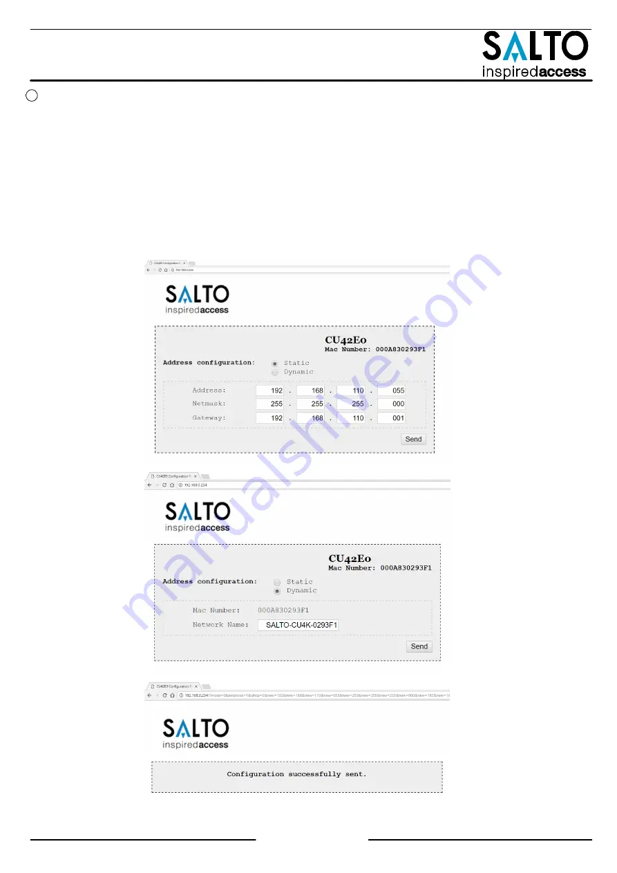
    3.2. The CU42E0 is a DHCP ready device. If there's no DCHP server, the user can manually set up a static IP address using a web
           browser.
           3.2.1. Press the CLR button for 5 seconds to access the addressing mode (LED ON will blink orange).
           3.2.2. Access the IP address 192.168.0.234 with your web browser. Set up the network parameters and click on "send".
           3.2.3. The CU42E0 will leave the addressing mode automatically, but you can also leave the addressing mode manually by
pressing the CLR button for 5 seconds.
4. Use SALTO ProAccess software to detect the device (consult SALTO ProAccess Software user manual).

Eng

6/20

Summary of Contents for XS4 CU42 Series

Page 1: ...allation m canique Eng F E CU42E0 CU4200 TAMPER Electric box with tamper switch Caja el ctrica con detector de intrusi n o tamper Coffret lectrique avec interrupteur anti sabotage This installation ty...

Page 2: ...ear button ha de ser pulsado menos de 5 segundos si se cambia la configuraci n lector a adido conectado por Ethernet dispositivo conectado por BUS485 etc Para ello la alarma de tamper ha de estar acti...

Page 3: ...L2 RL3 RL4 DOOR state for DOOR1 RTE input for DOOR1 DOOR state for DOOR2 RTE input for DOOR2 Office input for DOOR1 Office input for DOOR2 Lock Relay for DOOR1 Tamper Alarm DLO and intrusion DOOR 1 Lo...

Page 4: ...rtie La CU elle seule consome 400mA D pendant de l installataion l installateur doit calculer l alimentation n cessaire Note 2 M me tension que l entr e Note 3 R sistance de pull up 1K Note 4 Consulte...

Page 5: ...UY2 Crimpar con la tapa hacia abajo Connecteur 3MTM ScotchlokTM butt UY2 Cr per avec le capuchon vers le bas E Eng F READER 1 A B TAMPER IN1 IN2 IN3 IN4 IN5 IN6 READER 2 RL1 RL2 RL3 RL4 C NC NO C NC N...

Page 6: ...uide Set up all the CU4200s with their dip switches and assign the IP address to the CU42E0 3 Adress the CU42E0 3 1 Press the CLR BUTTON CU42E0 to detect the readers and the connected CU4200 Check tha...

Page 7: ...oftware consultar el manual de usuario de usuario de SALTRO ProAccess SPACE 3 Direccionar la CU42E0 3 1 Pulsaci n corta del CLR en la CU42E0 para detectar los lectores y CU4200 conectados Comprobar qu...

Page 8: ...des Dipswitchs et attribuer l adresse IP la CU42E0 3 Adresser la CU42E0 3 1 Appuyer sur la touche CLR CU42E0 pour d tecter les lecteurs et les CU4200 connect es V rifier que les voyants des lecteurs...

Page 9: ...rminal en posici n ON y el resto de CU4200s han de tener este resistor en posici n OFF Configuraci n del dip switch Si la CU4200 est en mode d connect e les r glages du dipswitch doit tre teint avec l...

Page 10: ...ende del tipo de input configurado a trav s del software READER ON el lector comunica con la CU OFF el lector no comunica con la CU presione el bot n CLR para iniciar la detecci n RL1 RL4 ON rel activ...

Page 11: ...A B TAMPER IN1 IN2 IN3 IN4 IN5 IN6 READER 2 RL1 RL2 RL3 RL4 C NC NO C NC NO C NC NO C NC NO BUS485 Ethernet 10Base T 100Base TX ON 12VDC Input A B 12VDC Output 1A Power Input 12V DC 1A GND GND A B Mod...

Page 12: ...gd Ethernet verbonden of een apparaat is toegevoegd aan BUS485 enz De sabotagemelding tamper moet aanstaan om de configuratie te kunnen voltooien RS485 Bus eindweerstand is nodig ON positie wanneer de...

Page 13: ...r 1 T r ffnungstaster T r 1 T rkontakt T r 2 T r ffnungstaster T r 2 Eingang f r Office Mode T r 1 Eingang f r Office Mode T r 2 Ausgangsrelais T r 1 Sabotagealaram T r zu lange offen und Einbruch T...

Page 14: ...lektrische sluitplaat 1 2 3 1 2 3 1 2 3 READER 1 A B 12VDC Input TAMPER IN1 IN2 IN3 IN4 IN5 IN6 READER 2 RL1 RL2 RL3 RL4 A B C NC NO C NC NO C NC NO C NC NO BUS485 Model CU4200 12VDC Output 1A ON Powe...

Page 15: ...en gebruik wordt gemaakt van de 12 V uitgang De controller alleen verbruikt 400mA Afhankelijk van de aangesloten componenten moet de installateur een geschikte voeding berekenen en plaatsen Opm 2 Eve...

Page 16: ...R Taster einmal kurz wenn der Sabotagekontakt offen ist Die LED s m ssen einmal kurz aufleuchten 3 2 CU42E0 ist DHCP Vorbereitet In Werksauslieferung ist der DHCP Modus aktiviert Wenn der Kunde keinen...

Page 17: ...instellingen en ken het IP adres toe aan de CU42E0 in de software 3 Adresseer de CU42E0 3 1 Klik de CLR knop kort in om de aangesloten lezers te detecteren controleer of de oranje led op de lezers gek...

Page 18: ...aljer St ll in dip switcharna f r alla CU4200 och tilldela IP adress till CU42E0 3 Adressera CU42E0 3 1 Tryck p CLR knappen CU42E0 f r att detektera l sarna och den anslutna CU4200 Kontrollera att l s...

Page 19: ...begin en eind van de 485BUS moeten de eindweerstanden op de ON positie staan Een CU4200 of CU42E0 die tussen begin en eind van de bus zijn geplaatst moet de eindweerstand op OFF staan Dipswitch setup...

Page 20: ...ntroller is niet juist gevoed controleer de voeding KNIPPEREND ORANJE adressering modus UIT Geen voeding BUS485 AAN op CU4200 De controller communiceert met de CU42E0 AAN op CU42E0 Worden gedefinieerd...

Reviews: