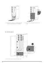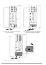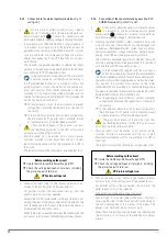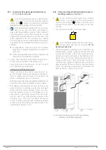
32
SALICRU
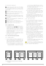
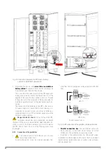
The steps required for unpacking are:
1
To unpack the equipment, cut the strips of the cardboard
enclosure and remove it from above as if it were a cover (
) or disassemble it with the necessary tools if the enclosure
is made of wood.
2
Remove the corner pieces and the plastic cover (
).
3
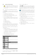
Remove the base sockets to expose the 4 legs in order to
release the equipment from the pallet (
4
Unscrew the 4 screws located on the inside of each of the 4
legs. The equipment will be released from its pallet and ready
for transfer (
5
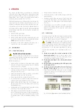
Proceed to lower the equipment from the pallet using a
6
Move the equipment to its final location (
7
Refit the 4 sockets on the base of the equipment (
).
8
Equipment unpacked in its final location (
5.1.4. Transport to the site
•
If the reception area is far from the installation site, it is
recommended to move the
SLC CUBE4
using a pallet truck
or another more suitable means of transport, assessing the
distance between the two points, the unit's weight, the
characteristics of the area to be crossed and the site (floor
type, floor resistance kg/m
2
).
•
However, when the distance is considerable, it is recom-
mended to move the unit in its packaging to the vicinity of
the installation site and then unpack it.
5.1.5. Siting, immobilisation and considerations
5.1.5.1. Siting for single units
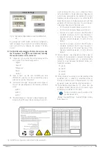
• By way of example,
shows configurations com-
posed of a single UPS cabinet: a UPS with batteries inside,
a UPS with an external battery cabinet and a UPS with
extended autonomy with two external battery cabinets.
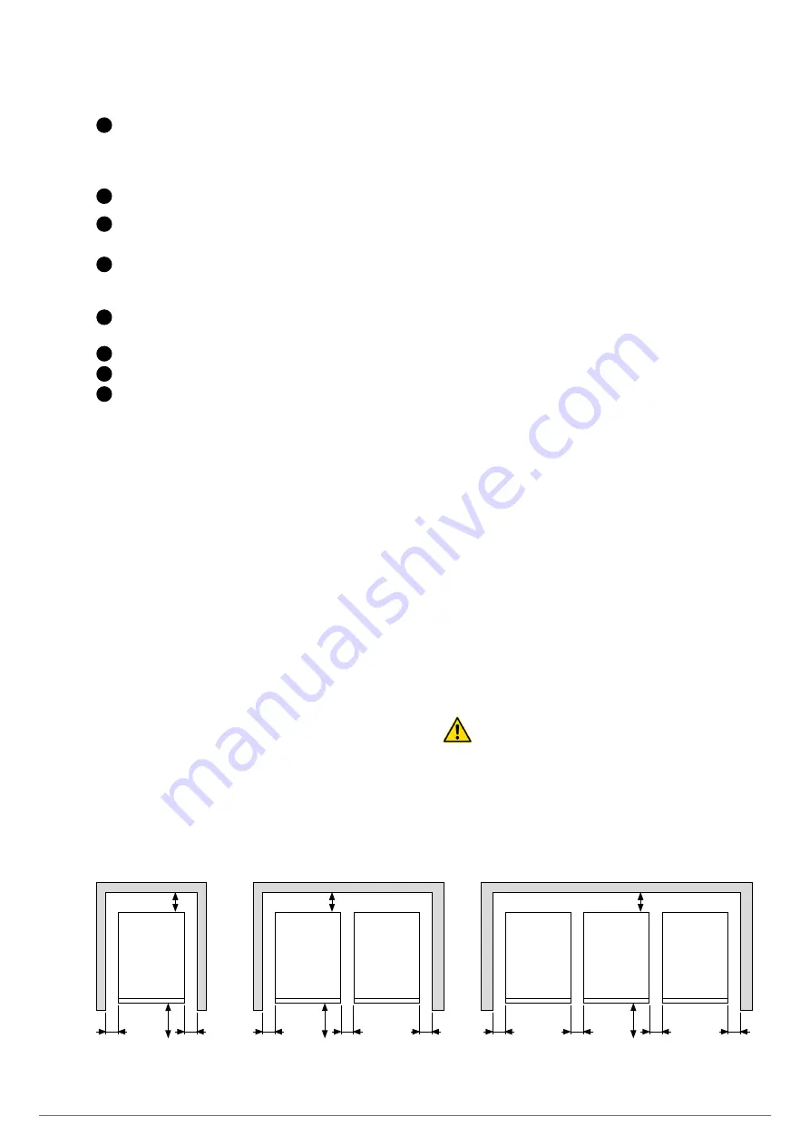
To correctly ventilate the unit, it is necessary to en-
sure its surrounding area is free of obstacles. Observe
the minimum distances indicated in the table in sec-
tion 1.2.1 of document EK266*08 (Safety instructions),
which indicates the values for dimensions A, B, C and
D according to the power of each unit.
For battery cabinets, keep the same distances as for
the UPS, which are configured by the system.
It is recommended to leave an additional 75 cm free on
the sides for any service interventions (T.S.S.) or the
required clearance for the connection cables to allow
the unit to be moved forwards.
For extended autonomy with more than one cabinet, it is
recommended to place one on each side of the unit, and in
the case of a greater number of battery cabinets, to repeat
the same sequence alternately.
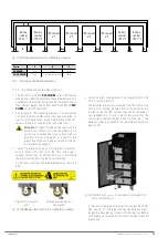
5.1.5.2. Siting for parallel systems
•
shows an example of 4 parallel units with their re-
spective battery cabinets. For systems with fewer units,
act accordingly on a case-by-case basis.
• It is recommended to place them in order according to the
number indicated on the door of each unit. The number cor-
responds to the original factory-assigned address.
This is not random, as due to the length of the battery
cables (3.5 m) and the communication BUS (5 m), this is
the optimal arrangement. For a greater number of battery
cabinets in systems with extended autonomy, follow the
same criteria, maintaining the symmetry.
• When the system is structured by models with the bat-
teries and unit mounted in the same cabinet, the illustra-
tions of the battery modules should be disregarded.
To correctly ventilate the unit, it is necessary to ensure
its surrounding area is free of obstacles. Observe the
minimum distances indicated in
, which indicates
the values for dimensions A, B and C according to the
power of each unit.
For battery cabinets, keep the same distances as for the
UPS, which are configured by the system.
For service work it is recommended to leave a distance
of 75 cm on the sides and to the rear (30 and 40 kVA) and
only on the sides (50 kVA, 60 kVA and 80 kVA).
C
B
A
A
UPS cabinet
with batte-
ries
C
B
A
A
A
UPS cabinet
Battery
cabinet
UPS
C
B
A
A
A
Battery
cabinet
UPS nº 1
Battery
cabinet
UPS nº 2
A
UPS cabinet
Fig. 36.
Minimum peripheral dimensions for ventilating
the UPS.


