


10
IV Ballast Installation
Part Number
Descriptions
Qty
00-9011-C11360*
SCREW, BUTTON HD SOCKET CAP SCREW, 18-8 SS, 10-32X1.25"
5
00-9003-C11359*
LOCKNUT, NYLON 18-8 SS, 10-32
5
06-1202-C11361A
SPACER, BALLAST 1/2" PLASTIC
2
06-1202-C11362A
SPACER, BALLAST .75" PLASTIC
3
Tools needed
•
¼ ” drive 1/8” Alan socket
•
¼” drive 3/8” deep socket
•
¼” drive 10 mm shallow socket
•
8” Extension, ¼” drive
•
¼” drive ratchet
•
Panel puller
•
Drill
•
Drill bit ¼”
•
Drill bit 1/8”
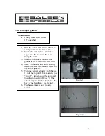
1.
Remove the fender liners. Figure 1 is
an over view where the push screws are
located. Figures 2 and 3 are close ups.
Use the panel puller to remove push
screws.
Figure 1
Figure 2
Figure 3


