AVA S/AVA DX/RFC/RWC v2024.1
10
| EN
5. INSTALLATION
5.1.
RECEPTION OF GOODS
Each device is carefully checked before transportation. When receiving the goods, checking the devices for any damage made during transporta-
tion is recommended. If any damage to the unit is observed, immediately contact the representatives of a transport company. Please inform the
representative of the manufacturer, if any deviation of the device is noticed.
5.2.
TRANSPORTATION AND STORAGE
•
All units are factory-packaged to withstand normal conditions of transportation.
•
When unpacking, check the unit for any damage made during transportation. Installing the damaged units is not allowed!
• The packaging is used for protection purposes only!
• When unloading and storing the units, use suitable lifting equipment to avoid damage and injuries. The storage place must be protected against
dirt and water.
• The recommended storage period should not be longer than one year.
5.3.
UNPACKING
• Open the box.
• Take out the unit of the box.
•
After unpacking the unit, examine it to make sure that no damage was made during transportation. Installation of damaged units is not allowed!
• Before commencing the installation of the unit, please check if all ordered equipment has been delivered. Any deviation from the ordered equip-
ment list must be reported to the product supplier.
5.4.
MOUNTING
Installing should only be performed by qualified and trained staff.
Coils are designed for mounting in horizontal position.
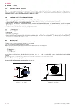
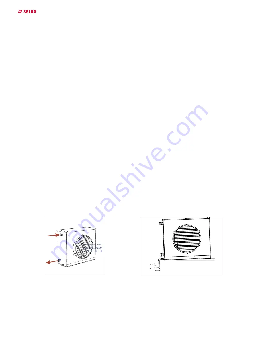
Water connection process should be processed using mounting scheme (see the scheme S1).
S1:
a - water flow in;
b - air flow;
c - water flow out.
When cooler is already mounted the draining system has to be connected. In order to do that siphon must be screwed to the cooler draining
exhaust.
The draining system should be filled up with at least 0,5 l of water (siphon must be always filled with water).
Check if water reaches sewerage system.
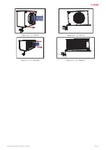
When installed, the cooler should have an angle of 0-3° (fig. S2).
~100 mm
~100 mm
0 - 3
o
a
b
c
~100 mm
~100 mm
0 - 3
o
a
b
c
Figure 5.4.1. S1 - AVA S
Figure 5.4.2. S2 - AVA S


