background image

19  |   

Sailrite�com

Leatherwork

®

 Guidebook 

 |  20

Thread Tension Adjustment

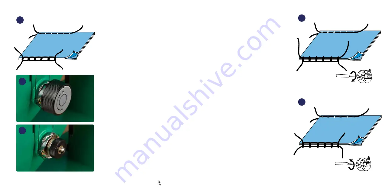
The correct combination of thread tension (

21

results in a stitch that looks identical on both sides of 

the material (i�e�, the knots of the stitches are pulled 

into the fabric and are no more visible on the top 

than on the bottom)�

If knots are visible on both the top and bottom 

material surfaces, this is an indication that the thread 

size is too large for the material being sewn�

The upper tension knob (

22

) can be loosened 

or tightened to adjust tension� Rotating the knob 

clockwise or toward the “+” will increase upper 

tension, pulling the knot to the top of the sewn 

application (

24

)� Rotating the knob counterclockwise 

or toward the “-” will decrease upper tension, 

allowing the knot to be pulled to the bottom of the 

sewn application (

25

)�

When the presser foot is lifted, the upper tension 

disks are pushed apart� This releases the top thread 

tension so leather can be removed from under the 

machine foot without fighting thread tension. 

DO NOT

 lift the presser foot when the upper tension 

knob is less than a 1/2 turn from maximum (turned 

snugly clockwise) (

23

)� This amount of tension 

should never be required�

If upper tension is tightened all the way down, 

raising the presser foot may bend the lever inside 

the machine that separates the disks, preventing the 

disks from opening correctly�

Knots centered — PERFECT STITCH

22

23

21

NOTE: Decorative cap removed�

Knots visible on bottom

Knots pulled to top

24

25

Advanced Thread  
Tension Adjustment

Before moving on, please reference 

p� 6 to ensure proper needle and 

thread size are being used for your 

application� 

Tension changes to the bobbin thread should 

only be made when upper tension changes alone 

do not solve stitch tension� In general, bobbin 

tension requires just about a 2 ounce drag on 

the thread (similar to what you feel when pulling 

dental floss off a spool).

If knots are pulled to the top (

24

) and you can’t 

loosen the upper tension knob (

22

) any more, 

remove the bobbin case from the machine and 

increase the bobbin case tension by tightening 

the tension adjustment screw (p� 14, 

I

)� Tighten 

in 1/4 increments, testing the drag on the 

thread after each 1/4 turn until proper tension 

is achieved�

If the knots are pulled to the bottom (

25

) and 

you can’t tighten the upper tension knob (

22

any more, remove the bobbin case from the 

machine and decrease the bobbin case tension by 

loosening the tension adjustment screw (p� 14, 

I

)� 

Loosen in 1/4 increments, testing the drag on the 

thread after each 1/4 turn until proper tension is 

achieved�

Summary of Contents for Leatherwork

Page 1: ......

Page 2: ...t 20 Adjusting Presser Foot Tension 21 Removing Material From Under the Presser Foot 21 Sewing Fabric 22 Leatherwork Maintenance 23 Lubrication 23 Troubleshooting the Leatherwork 27 Proper Needle Orientation Installation 27 Replacing Take Up Spring 28 Belt Issues 29 Material Surface Is Being Damaged 29 Clutch Will Not Disengage 30 Removing the Hook to Clean the Shuttle Race Guide Shaft Free Thread...

Page 3: ...hine around flammable materials Do not use a plug adapter or extension cord that bypasses the ground pin Always rotate the balance wheel by grabbing the top of the wheel and rotating toward the front of the machine Wire the light in a manner that keeps the cord clear of belts and other moving parts WARNING This product can expose you to chemicals including Nickel Metallic which is known to the Sta...

Page 4: ...g the machine When performing maintenance on the sewing machine turn the motor power switch to the OFF position and remove the power cord from the wall To avoid injury or damage to the motor do not alter or tamper with the internal components of the motor Do not cover the motor s ventilation it can cause the motor to overheat Changing Motor Rotation Make sure the motor is always running in a count...

Page 5: ...and needle being too large For woven textiles use our needle and thread recommendations available online in our Thread Needle Recommendation Guide You can find the guide on every fabric detail page or by searching 300032XHT at Sailrite com SPEED SETTING WORKHORSE SPM 5 45 6 55 7 64 8 73 9 82 10 91 11 100 12 110 13 119 14 128 15 137 16 146 17 155 18 165 19 174 20 183 21 192 22 201 23 210 24 220 25 ...

Page 6: ...most medium to heavy sewing Needle Types Needle Installation Leatherwork needles are round on top unlike home sewing machine needles As a result proper installation must be exercised carefully Improperly installed needles are the main reason users call for help The needles have two distinct sides One side has a long channel or groove running the length of the needle and the other side has a short ...

Page 7: ...ine 1 Thread comes off top of cone F to Thread Stand arm G 2 Pass through thread post H 3 Wrap around bobbin tensioner I 4 Run under and up through a hole in top of bobbin J Place bobbin on post and push to the right Hold onto thread tail briefly and power machine with the clutch disengaged to wind bobbin Stop after several rotations and cut the thread tail off flush with the bobbin side 5 Continu...

Page 8: ...ightmost hole skipping middle hole and bringing thread around front and down again through the leftmost hole E 5 Thread through upper tension shown without cover knob F Make sure lift lever G is raised up to release tension plates so thread can pass through Be sure to catch the hooked spring end with the thread last 6 Pass through take up arm right to left H and then under end cover I 7 Pass throu...

Page 9: ...bbin case is pushed completely in place there is a clicking sound when the case is pushed all the way on The finger of the bobbin case will drop into the notch in the hook s retaining ring H Bobbin thread should loosely dangle B G H E I 11 Installing Bobbin in Bobbin Case 1 Insert a threaded bobbin A into the bobbin case B as shown in image 12 2 Hold the tail of the thread while pushing the bobbin...

Page 10: ...chines arrive tuned and optimized for sewing leather If you want to sew other materials you will need to make adjustments Refer to Sewing Fabric section p 22 Starting to Sew 1 Plug the machine into an outlet and switch the Workhorse Servo Motor on 2 Use the lift lever 18 to raise A and lower B the presser foot onto the material 3 The thread ends from the needle and the bobbin should be behind the ...

Page 11: ...will cause a skipped stitch or needle deflection Rotating the leather fabric while the machine is at rest with the presser foot down may bend the needle Regulating Stitch Length The EZ Set Stitch Length Plate 20 sets both forward and reverse stitch length To set the stitch length loosen the two thumbscrews A slide the posts up or down and tighten the screws The thumbscrew stops B restrict the move...

Page 12: ...f upper tension is tightened all the way down raising the presser foot may bend the lever inside the machine that separates the disks preventing the disks from opening correctly Knots centered PERFECT STITCH 22 23 21 NOTE Decorative cap removed Knots visible on bottom Knots pulled to top 24 25 Advanced Thread Tension Adjustment Before moving on please reference p 6 to ensure proper needle and thre...

Page 13: ...ds to free the material leaving at least an 8 inch length of thread coming out of the machine More than two threads See p 36 28 26 27 Adjusting Presser Foot Tension The amount of downward pressure put on the material by the presser foot is controlled by the Pressure Regulating Thumbscrew A This screw compresses a long coil spring above the presser foot Turn the screw clockwise to increase the down...

Page 14: ...and maintaining the Leatherwork Sewing Machine With regular use Super Lube will help your machine operate more smoothly last longer and sew more quietly After oiling briefly sew with scrap material to prevent soiling your work For good maintenance of your machine you should oil it approximately every 8 hours of use before it is put in storage or anytime the machine sounds like it is running roughl...

Page 15: ...Left end and back side lubrication points 31 Underside lubrication points 32 Leatherwork Guidebook 26 25 Sailrite com ...

Page 16: ...ide the new take up spring over the core post K so that the pip on the back faces in toward the machine and the straight arm of the spring faces down approximately at a 6 o clock position Push the spring in all the way 6 Spin the arm of the spring clockwise past the slot in the plastic core 7 While holding the spring arm in place slide the keyway washer I back onto the core with the pip facing in ...

Page 17: ...requires adjustment it should be done first Move the Idler Pulley B down to tighten the long belt To do so loosen the pulley shaft C using the box wrench provided and slide the pulley on its bracket 35 Tighten when done To adjust the shorter belt D loosen the screw E in the curved slot above the motor pulley end in the aluminum bracket 35 Pivoting the motor back will tighten the belt between the m...

Page 18: ...he presser feet and continue sewing Follow these directions to avoid badly tensioned corner stitches and reduce the chance of a skipped stitch 3 Not Enough Foot Pressure Materials like dense vegetable tanned leather can make the withdrawal of the needle from the material difficult If the presser foot is being lifted as the needle comes out of the leather the loop that the needle forms will be too ...

Page 19: ... needle eye to form a loop and will instead ball at the needle Check the compatibility of the needle size and thread weight p 6 39 5 Replace the needle making sure installation is correct See p 8 6 Burred Shuttle Gib Hook or Retaining Ring Cap Spring A machine crash or needle strike to the Shuttle Gib Hook A or Retaining Ring Cap Spring B may result in a burr or damage which can cause the thread t...

Page 20: ...onfirm that the needle eye is threaded from left to right p 11 10 K Then pull out a longer thread tail and trap it with your finger to the bed of the sewing machine A Release the thread tail after the first few stitches A rat s nest forms in the first few inches of sewing and then clears up Eliminate this issue by trapping the thread tails A from the needle and the bobbin as you start to sew 41 Wh...

Page 21: ...shed all the way into the bushing hole that locks the bushing to the balance wheel or if the bushing itself is loose 1 Make sure the Posi Pin A is fully inserted 2 If slipping still occurs remove the Posi Pin A and Posi Pin nut B and slide the balance wheel C off the bushing Use a 2 5mm hex key to tighten the two set screws p 59 17 that fasten the bushing to the machine s upper shaft then reinstal...

Page 22: ...erate the machine to move the needle bar to the bottom of its stroke all the way down 2 Unlock the needle bar from the drive collar B by loosening the set screw that can be accessed through a hole in the machine casting D Use a 2 5mm hex key to loosen 3 With the needle bar at the bottom of its stroke reposition the needle bar so the score on the needle bar lines up with the top surface of the uppe...

Page 23: ...ntinue to adjust the driver p 42 Hook Driver Gap Oscillating hook sewing machines have loose tolerances between the Shuttle Gib Hook and the Shuttle Driver This play between the parts is intentional and allows the Leatherwork to sew a wide variety of thread sizes The typical play between parts is 0 04 inch 47 B A F C E D 48 Adjust the Driver 4 The driver is secured to the lower shaft with two set ...

Page 24: ...machine 49 slowly rotate the balance wheel As the gib hook A swings past the needle the hook should be as close as possible to the right side of the needle without deflecting it B If the gap between the needle and the hook is too large the hook must be moved to the left to close the gap See p 45 to make adjustment If the needle is being deflected by the hook then the hook must be moved to the righ...

Page 25: ...ht as possible just resting on the frame Tighten the two collar screws There should be practically no side to side play in the center shaft H To move the hook away from the needle 2 Loosen the two screws in the right collar G and move it to the left on its shaft and move the shuttle assembly D to the right 3 Move the assembly D to position the hook as close to the needle E as possible without defl...

Page 26: ...djust the Rotational Positioning of the Shuttle Race Guide Shaft 1 First determine that there is no more than 1 64 inch of play in the left right movement of the lower shaft C If there is more than 1 64 inch play refer to p 43 2 Rotate the balance wheel until the needle enters the shuttle 53 3 With left hand grab the Shuttle Race Guide Shaft D hold to the right and maintain light pressure 4 With r...

Page 27: ... 12 Set Screw 103640 13 Left End Plate W048 14 Screw C097 15 EZ Set Stitch Length Plate 105511 16 Stitch Length Plate Screw 103263 17 Needle Plate 5mm W032 18 Needle Plate Screw A052 19 Shuttle Race Slide 120346 20 Three Hole Thread Guide W029 21 Upper Tension Assembly includes 24 8511 22 Thread Guard Screw 103253 23 Top Plate Set Screw E072 24 Thread Take Up Spring included in 21 5332 25 Tension ...

Page 28: ...r Spring A032 20 Needle Bar Support B016 21 Needle Bar Set Screw D097 22 Zigzag Connecting Rod W015 23 Needle Bar Connecting Joint Pin B099 24 Needle Bar W066 25 Needle Thread Guide W067 26 Needle 135X16 N A 27 Presser Foot Screw A036 28 Inside Presser Foot W012 29 Presser Bar A035 1 30 Presser Bar Lower Bushing B028 31 Presser Bar Bracket W039 32 Presser Bar Feed Actuator Pivot Screw 103257 33 Te...

Page 29: ...Clamp B155 11 Compressible Timing Clamp Pin A084 12 Compressible Timing Clamp Screw B153 13 Shuttle Race Guide Shaft B170 14 Lower Shaft B172 15 Shuttle Driver W172 16 Shuttle Gib Hook 9601 17 Bobbin 123100 18 Bobbin Case Assembly 1232 19 Screw B139 2 20 Retaining Ring Cap Spring 1603 21 Retaining Ring Clip Set 123011 22 Retaining Ring Clip Spring 103273 23 Retaining Ring Clip Screw 103274 24 Reta...

Page 30: ...ating Shaft Set Screw Nut A023 12 Driving Crank W046 13 Feed Rock Shaft Crank A071B 14 Feed Rock Shaft A071A 15 Feed Bar Center Screw Nut A076 16 Feed Bar A075 17 Feed Dog Screw A078 18 Knurled Feed Dog 121395 19 Driving Crank Guide Nut W046 1 20 Driving Crank Guide Screw A061 21 Feed Lifting Rock Shaft A072 22 Feed Lifting Rock Shaft Crank A073 23 Screw B139 2 24 Feed Regulator Wavy Washer A067 2...

Page 31: ...nd Plate Set Screw W041 1 22 Presser Foot Bracket Limiter W014 23 Screw C097 24 Presser Bar Feed Rod W036 25 Presser Bar Actuator Spacer W024 1 26 Bearing Bracket Bushing W021 27 Lift Crank Rod Bearing Plate W023 28 Rocker End Set Ring W052 29 Presser Bar Actuator Rocker W033 30 Presser Bar Actuator Feed Rocker W034 31 Crank Rod Rocker W035 32 Crank Rod W053 33 Set Screw 103640 34 Screw A036 or 10...

Page 32: ...3 16 100538 6 Power Plus Flywheel 100181 7 E5 Ring D116 8 Idler Pulley Shaft W061 1 9 Idler Pulley W061 A 10 Idler Pulley Washer W061 6 11 Idler Pulley Set Nut W061 2 12 Pulley Bracket W059 13 Bracket Washer LT 2M 4 14 Bracket Lock Washer LT 2M 3 15 Bracket Bolt LT 2M 2 16 Screw W049 1 17 Set Screw 713100 18 Idler Pulley Leatherwork L Bracket 121448 19 Washer 121444 20 Compression Spring 121443 21...

Page 33: ... Head Wood Screw 103528 9 Flat Head Screw for Oil Tray 120462 10 Sheet Metal Screw Slotted 14x1 100845 11 Spring Lock Washer 100844 12 Flat Washer 100842 13 Square Neck Carriage Bolt 1 4 x2 122533 14 Washer 1 4 122535 15 Hex Nut 1 4 122534 16 Flex20 LED Light 121767 17 Extension Cord for Flex20 121815 110V or 121816 220 240V 1 2 Idler Pulley See p 59 5 6 16 17 7 9 10 11 12 13 14 12 15 7 Not to Sca...

Page 34: ... 4 5 Presser Foot Lift 3 8 0 375 Bobbin Size Class 15 Style A 20 5mm Dia x 10 8mm H Needle Size Range 10 22 Thread Range Home Sizes to V 92 T 90 Workhorse Servo Motor Specifications Voltage 110 120V or 220 240V check motor to confirm voltage H P 0 75 Power 550W Power Consumption 4 5 amps Motor RPM 4 500 Speed Control Digital Sailrite Pulley Cogged Pulley Type 21 Tooth Timing Pulley Pulley Diameter...

Page 35: ...ug the motor remove the front external plastic cover and replace the main fuse with one of the extras sent with the motor If the problem continues to persist please contact Sailrite E5 Needle position problem 1 Press and release the S button and the LED display will change to P 2 Press the P button 2 times and the display will change to n1 3 Press the S button and the display will change to 1 4 Pr...

Page 36: ... costs of replacement parts If sending the Leatherwork back to Sailrite headquarters for repair the customer is responsible for all shipping costs to and from Sailrite Please insure the machine in transit The machine should be shipped in the original packaging to ensure safe transport The Leatherwork machine head and Workhorse Servo Motor limited warranties do not cover any damage that results fro...

Page 37: ...th everything you need to successfully maintain and repair your Leatherwork Sewing Machine Your purchase comes with personalized support for the lifetime of your machine We will do our best to satisfy every support request accurately completely and in a timely manner Customer Service Questions or Concerns To start a support case go to Sailrite com support and fill out the online form One of our su...

Reviews: