background image

5

Installation

C4900/01

2.3.3

Connection of Transceiver / Indoor and Weatherproof Handset

If the existing handset hook is the one shown in the drawing below, your weatherproof handset is to be connected as
follows.

37391

Transceiver

56.114

Indoor

Outdoor

WP

X1

supplied by the factory

10m cable

US

1W

TX

ALARM

CALL

TX 1W US

CALL

ALARM

WARNING:

Do not connect the spiral cable for the intelligent handset directly to the transceiver. The spiral cable for the intelligent
handset must be connected to the handset hook; otherwise the transceiver may activate distress.

0025

Summary of Contents for C4900

Page 1: ...SAILOR C4900 C4901 Installation Manual ...

Page 2: ...rements within the concept of GMDSS as to operation of equipment and basic understanding of the systems is an extremely important factor for the overall success ful implementation of GMDSS As a unique initiative for GMDSS solutions we can supply a complete software training programme for on board training to be used as preparation in order to fulfil the GMDSS requirements for obtaining the General...

Page 3: ...therproof Handset 6 2 4 2 Connection of Transceiver Connectionbox H4991 Indoor and Weatherproof Handset 7 2 5 Loudspeaker Connection 8 2 6 Connectors 8 2 6 1 SPARC Bus Cable 9 2 7 Installation of Handset 10 2 8 System Function Test 12 2 8 1 Test Procedure System Priorities System Control and SPARC Bus Data Interface Circuits 12 2 8 2 Test Procedure Intercom Handset TX AF Circuits and Handset Audio...

Page 4: ... Space for handset access min 200 Space for cable and handset cable CALL TX US 1W ALARM 4 0 35556 34 123 52 5 2 x ø4 5 ø12 for cable entry 144 13 5 Weight Handset 0 5 kg 2 2 Power Supply The handset unit is supplied from the SPARC bus interface with 12V DC The 12V DC supply is fused in the handset by a 630 mA fuse 9915 ...

Page 5: ...hooks or to be connection box H4991or WP SPARC bus connection box The max number of handsets allowed to be connected simultaneously to the transceiver without DSC are 4 handsets and to the transceiver with DSC are 7 handsets 2 3 1 Connection of Transceiver Indoor Handset 37389 Transceiver X1 56 114 Indoor TX 1W US CALL ALARM WARNING Do not connect the spiral cable for the intelligent handset direc...

Page 6: ...ARNING Do not connect the spiral cable for the intelligent handset directly to the transceiver The spiral cable for the intelligent handset must be connected to the handset hook otherwise the transceiver may activate distress 0025 When connecting the sub D plug it is possible to avoid making a big hole in the bulkhead of the ship by installing a WP SPARC Bus connection box between the transceiver ...

Page 7: ... is to be connected as follows 37391 Transceiver 56 114 Indoor Outdoor WP X1 supplied by the factory 10m cable US 1W TX ALARM CALL TX 1W US CALL ALARM WARNING Do not connect the spiral cable for the intelligent handset directly to the transceiver The spiral cable for the intelligent handset must be connected to the handset hook otherwise the transceiver may activate distress 0025 ...

Page 8: ...o be connected simultaneously to the transceiver with DSC are 6 handsets Always connect local handset to the transceiver DSC Class of intelligent handset is D even if the radio is Class A 2 4 1 Connection of Transceiver Indoor and Weatherproof Handset 35406C 56 114 Transceiver Indoor Outdoor WP supplied by the factory 10m cable US TX 1W CALL ALARM SPARC BUS HANDSET PRINTER OPTION Tx Rx 12V DC TX 1...

Page 9: ... cable supplied by the factory HANDSET SPARC BUS 12V DC OPTION PRINTER Tx Rx US 1W TX CALL ALARM US TX 1W CALL ALARM TX 1W US ALARM CALL WARNING Do not connect the spiral cable for the intelligent handset directly to the transceiver The spiral cable for the intelligent handset must be connected to the handset hook otherwise the transceiver may activate distress 0025 ...

Page 10: ...eaker selection is made by the control unit s 2 6 Connectors Handset Hook SPARC Bus Connection Box H4991 WP SPARC Bus Connection box 35348 _ON Term ON VDC 12 LS_1 LS_1 LS_2 LS_2 BAT AF AF _AF RX BAT _AF RX SPARC _ON SUPPLY VDC 12 RX_AF RX_AF 12VDC BAT AF BAT AF SPARC LS_2 LS_2 _1 LS _1 LS SUPPLY HOOK Connection 32262 SPARC SPARC 12VDC X2 5 1 2 3 4 13 14 15 X3 6 7 8 10 11 9 S3 10 11 12 6 7 X1 8 9 R...

Page 11: ...QVFHLYHU 22 PHWUHV The SPARC bus cable length is limited by the level of output power delivered to a connected external speaker on the LS_2 terminals The speaker output power depends on cable length and cable thickness as described in the table below LUH PP HQJWK P 0D 3RZHU 35356 56 114 SPARC bus Option cable 5 metres 56 114 3LQ QR 1DPH RORXU 7ZLVWHG SDLU SLQ 6833 B21 5HG KLWH SLQ 63 5 HOORZ SLQ 6...

Page 12: ... 15 pole D sub connector and place the handset on hook 2 Turn the VHF system on by pressing the ON OFF button at the top of the handset 3 Set up the handset SPARC bus location number and SPARC bus handset name by entering the service menu in the handset Press Press arrow down Press Key in the acces code Alter the key until the digit appears Press Press ___ TELEPHONY FUNC ___ SERVICE FUNC ___ BUS S...

Page 13: ...ernal speaker has to be linked to the handset Enter the function menu and select external speaker as desired Path Func general sound loudspeak norm alarm extspk Display Use to change type of EXT speaker 0 No external speaker selected 1 External speaker 1 selected 2 External speaker 2 selected 3 Both external speakers selected Use to select the setting ___ LOC NO 1 SELECT FUNC ___ NAME FUNC 16 0 08...

Page 14: ...ormed succesfully the VHF system functions correctly Purpose To test correct assembly of the system ensuring SPARC bus command communication between all system units including system control priorities for the control units Check the telephony TX LF and RX LF routing Test setup Turn on all control units all handsets placed on hook each unit showing VHF display 2 8 1 Test Procedure System Prioritie...

Page 15: ...l control units VHF display system idle Hook on 3a Handset loc_2 Handset loc_2 VHF display Hook off Other control units OCC display 3b Handset loc_1 Handset loc_1 or loc_2 VHF display Hook off Other control units OCC display 16 0 08 01 MEM VOL SQ 16 0 08 01 MEM VOL SQ 16 0 08 01 MEM VOL SQ oCC 2 NAME 16 0 08 01 MEM VOL SQ oCC 1 NAME oCC 1 NAME 0010 ...

Page 16: ...play Hook on Other control units OCC display 3f Handset loc_2 All control units VHF display system idle Hook on All on hook If the different control units do not act as described it is possible that some of the units are assigned the same location number if so check the location number setup in each unit 16 0 08 01 MEM VOL SQ oCC 2 NAME 16 0 08 01 MEM VOL SQ oCC 2 NAME 16 0 08 01 MEM VOL SQ oCC 2 ...

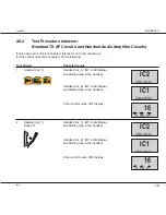
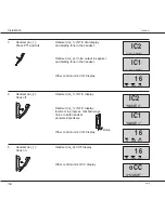
Page 17: ...lt 1 Handset loc_1 Handset loc_1 INT C dial display and dialling tone in the handset Handset loc_2 INT C dial display and dialling tone in the handset Other control units VHF display 2 Handset loc_1 Handset loc_1 INT C dial display Hook off and dialling tone in the handset Handset loc_2 INT C dial display and dialling tone in the handset Other control units VHF display IC2 CALLING IC1 CALLING 16 0...

Page 18: ...its VHF display 4 Handset loc_2 Handset loc_1 INT C display Hook off Handset loc_1 INT C display Intercom in progress talk both ways Voice in both handset earpieces speakers Other control units VHF display 5 Handset loc_1 Handset loc_2 VHF display Hook on Other control units OCC display IC2 CALLING IC1 CALLING 16 0 08 01 MEM VOL SQ IC2 NAME 2 IC1 NAME 1 16 0 08 01 MEM VOL SQ 16 0 08 01 MEM VOL SQ ...

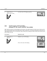
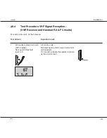
Page 19: ...y no light in the 1W indicator lamp If the VHF transmitter fails the 1W indicator lamp will go on during PTT push and or the display will show the error message ANTN FAIL This is not the expected result If ANTN FAIL is displayed check that the aerial and aerial cable are connected correctly Test stimuli Expected result 1 Handset loc_1 Handset loc_1 VHF display Hook off Other control units OCC disp...

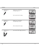
Page 20: ...ther control units OCC display 3 Handset loc_1 Handset loc_1 VHF display Release PTT TX indicator lamp turns off Other control units OCC display 4 Handset loc_ 1 All control units VHF display system idle Hook on oCC 1 NAME oCC 1 NAME 67 0 08 01 MEM VOL SQ 67 0 08 01 MEM VOL SQ 67 8 08 01 MEM VOL SQ 0010 ...

Page 21: ... For each control unit do the following Test stimuli Expected result 1 All handsets placed on hook All control units VHF display Receiver opens static noise in all control Set squelch threshold unit speakers level to 0 If no sound activate the speaker and turn up the volume level 67 0 08 01 MEM VOL SQ 0010 ...

Page 22: ... int path Select call by arrow right key 3 Transmit the call by keying Send call 4 The display will show in sequence TX CALL TX OK 5 The call is announced by the DSC modem Read the call info in RX LOG External test call The call is transmitted and received using the aerials This test also controls the hardware of transmitter and receiver boards 1 Hook off handset 2 Enter function menu Func dsc tes...

Page 23: ......

Page 24: ......

Reviews: