Saia-Burgess
Controls Ltd.
Hardware Manual for the PCD3 Series│Document 26/789; Version E 5│31.01.2005
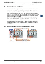
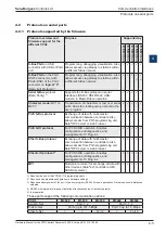
Communication interfaces
4
4-10
Serial interfaces on I/O module Slot 0
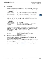
4.5.2 RS 485 with PCD3.F150
PCD3.F150:
RS 485 electrically isolated, with line termination resistors
capable of activation, for I/O module Slot 0. To move the
jumper (activate line termination resistors), the module
housing has to be opened, as described in
section 5.1.5
,
to reach the PCD7.F150 circuit board.
The electrical isolation is achieved with 3 optocouplers and a DC/DC transducer.
The data signals are protected against surges by a suppressor diode (10V). The line
termination resistors can be connected/disconnected with a jumper.
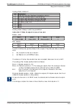
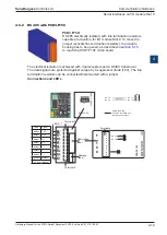
Connections and LEDs
F
PCD3.F150
0
1
2
3
4
5
6
7
8
9
LED 0...7
1
5
0
0
1
2
3
4
5
6
7
RX - TX
/RX - /TX
����
50 VDC
����
50 VDC
����
50 VDC
RX - TX
/RX - /TX
RX - TX
/RX - /TX
Bus RS 485
D
/D
SBUS
SGND (galv. sep.)
has to be connected with
the shield of the cable
J1
OPEN
CLOSED
PCD7.F150
Terminal 0
Description-
label
Address-
label
Terminal 9
Terminals
Colour
Signal
amber
TXD
amber
RXD
amber
n.r.
amber
n.r.
amber
n.r.
amber
n.r.
amber
n.r.
green
Detect
n.r. = not relevant


