background image

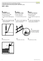
W

O

 - 14 mm

W

O

L

O

 - 14 mm

L

O

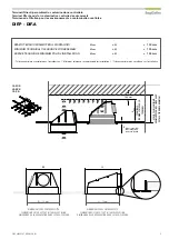
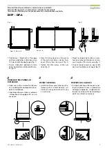
DIMENSIONI FORO CONTROSOFFITTO

DIMENSIONS OF THE CUT OUT IN THE FALSE CEILING

DIMENSIONS DE LA RÉSERVATION DANS LE FAUX-PLAFOND

DIMENSIONI FORO CONTROSOFFITTO

DIMENSIONS OF THE CUT OUT IN THE FALSE CEILING

DIMENSIONS DE LA RÉSERVATION DANS LE FAUX-PLAFOND

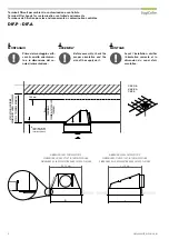
100 mm

H

max

TERMINALE

TERMINAL FIL

TER HOOD

TERMINAL

telaio controsoffitto

    false ceiling frame

    cadre faux-plafond 

SP

AZIO TECNICO 

MINIMO

MINIMUM TECHNICAL 

CLEARANCE

ESP

ACE TECHNIQUE 

MINIMUM

CASO B

CASE B

CAS B

DIF.P - DIF.A

SIEF_20200507_DIF.P-DIF.A _M

5

Terminali filtranti per ambienti a contaminazione controllata

SPAZIO TECNICO MINIMO PER IL MONTAGGIO

max


  +   H   


    +   100 mm

* Tolleranza minima consigliata per l’installazione 

 / * Minimum tolerance recommended for installation

  / * Tolérance minimale conseillée pour l’installation

Terminal filter hoods for contamination controlled environments

MINIMUM TECHNICAL CLEARANCE FOR ASSEMBLY 

max


  +   H   


    +   100 mm

Terminaux de filtration pour les environnements à contamination contrôlée

ESPACE TECHNIQUE MINIMUM POUR L’INSTALLATION

max


  +   H   


    +   100 mm

Summary of Contents for DIF.P

Page 1: ...EMBLY INSTALLATION INSTRUCTION AND MAINTENANCE MANUAL The procedure listed into this manual should be carried out by qualified personnel and we recom mend to use relevant indi vidual protection device...

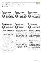
Page 2: ...RALE OU SUP RIEURE Terminal filter hoods for contamination controlled environments 1 HANDLING To avoid any possible dam age to the filters during the installation of the housings we recommended to ke...

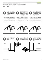
Page 3: ...ne di entrambe le pellicole1 2 Terminal filter hoods for contamination controlled environments 2 REMOVE THE PROTECTIVE FILM CASO A Only remove the spigot film1 Removal of the film below 2 ONLY BEFORE...

Page 4: ...rosoffitto false ceiling frame cadre faux plafond CASO A CASE A CAS A DIF P DIF A SIEF_20200507_DIF P DIF A _M 4 Terminali filtranti per ambienti a contaminazione controllata 3 MONTAGGIO Prima del mon...

Page 5: ...UM TECHNICAL CLEARANCE ESPACE TECHNIQUE MINIMUM CASO B CASE B CAS B DIF P DIF A SIEF_20200507_DIF P DIF A _M 5 Terminali filtranti per ambienti a contaminazione controllata SPAZIO TECNICO MINIMO PER I...

Page 6: ...tige filet e Terminal filter hoods for contamination controlled environments A By means of 4 M5 threaded rods screwed to the relevant bushes on the upper part of the profile 1 B Installation with bra...

Page 7: ...ble duct at least 20 mm away from the connec tion between the plenum and the spigot See figure below Connect the plenum spigot with the flexible duct and secure it in place with a clamp Secure the cou...

Page 8: ...cessary handle them care fully 3 Pay special attention to the gasket which must be unbroken before instal lation 4 Bring the filter still in its bag close to the cabinet 5 Open the bag and take the fi...

Page 9: ...lter hoods for contamination controlled environments Place the fixing devices io the groove of the aluminium frame placing them about 100 mm from the corners fig 1 Tighten the filter clamps all the wa...

Page 10: ...cate which should be kept 3 After thorough cleaning of the room switch on the ventilation system until the required class of cleanliness ac cording to ISO 14644 4 has been rea ched and maintained TIPS...

Page 11: ...per ambienti a contaminazione controllata Optional tests Reference in ISO 14644 3 2005 Referenced in Principle Procedure Apparatus Installed filter system leak test 4 2 4 B 6 C 6 ISO 14644 2 Terminal...

Page 12: ...qualsiasi momento senza alcun obbligo di preavviso per quanto indicato nella presente pubblicazione SagiCofim S p A reserves the right to make amendments or changes to the contents of this document at...

Reviews:

Related manuals for DIF.P