background image

6

5 System configuration

5.1

Device Management

Add Thermal Imaging Camera on System Tools via Device Management Interface:

STEP

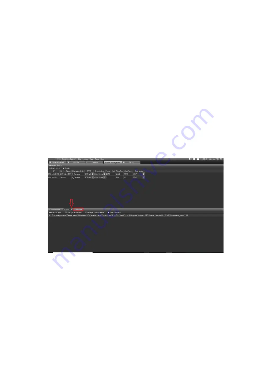
1: Add the thermal camera

Please refer to the figure picture, choose the protocol “mac-p” to search thermal camera on
Device Management Interface;

Remark:

1. Disable PC’s Automatic acquisition of IP addresses, set PC’s Lan local network IP

address as the same segment as thermal camera’s;

2. Default IP address of the thermal camera is 192.168.1.63;

Figure 3 Search and add the TI cameras to be managed

3. Double click the shown-up device on the list, and input user name and password;

The Default user name is “admin’, password is “admin123”;

If password forgotten after added the thermal camera on the tools, please reset
thermal camera by press “RST” button for few seconds, then the added thermal
camera will be shown on the list.

STEP 2: Add visible camera

1) Search visible camera via “Onvif” protocol

Summary of Contents for KIT-BODYTEMP-BLACKBODY

Page 1: ...1 Thermal Imaging Body Temperature Measurement System KIT BODYTEMP BLACKBODY User Manual...

Page 2: ...d add the visible light camera to be managed 7 Figure 5 Online preview of the dual spectrum camera 7 Figure 6 Set the referential point blackbody 8 Figure 7 Set the points to match the TI and visible...

Page 3: ...tem Microsoft Windows 7 and above version CPU 3 4 GHz or higher RAM 4G or higher Display 1024 768 resolution or higher 2 Features 1 Multi objects detection Face recognition with smart tracing which ca...

Page 4: ...pture 3 grades alarm setting voice alarm with capture Other Parameters Video setting alarm value setting display mode setting display zone setting blackbody calibration temp setting History Data Query...

Page 5: ...he adapter block on blackbody then put it on the tripod Set the blackbody on the entrance of passenger way height at approx 2m Blackbody is powered by AC 220v 2 You also can choose other installation...

Page 6: ...rk IP address as the same segment as thermal camera s 2 Default IP address of the thermal camera is 192 168 1 63 Figure 3 Search and add the TI cameras to be managed 3 Double click the shown up device...

Page 7: ...s 192 168 1 64 Figure 4 Search and add the visible light camera to be managed 2 Double click the shown up device on the list and input user name and password The default user name is admin password is...

Page 8: ...6 Set the referential point blackbody 5 3 Thermal Visible camera view field matching The purpose of this step is to establish the matching between the thermal imaging and visible light camera video p...

Page 9: ...istent If not readjust the position of Sp1 and Sp2 Then click position correction Sp1 Sp2 4 After the temperature alarm overlaps in the same position of the visible image click the real time mark mode...

Page 10: ...Figure 9 Set the multi levels over temperature alarming threshold 1 The information bar on the right side of the system interface sets the third level alarm temperature as 33 When an object is higher...

Page 11: ...ation bar on the right will be displayed 4 Click the capture checkbox and select the alarm level to automatically capture the image The snapshot information is at the bottom of the system Double click...

Page 12: ...upgrade function is to upgrade the firmware version of the camera modules and boards 1 Enter Remote configuration click on Remote upgrade 2 Please refer to the following figures steps Figure 11 To en...

Page 13: ...13 Figure 12 Click maintenance and then Remote upgrade 5 6 1 DSP Firmware upgrade Choose the corresponding file click open to upgrade...

Page 14: ...14 Figure 13 Upgrade the DSP firmware After the progress bar shows 100 it returns to zero red box 1 When the red box 2 appears on the screen restart the device red box 3...

Page 15: ...ilicon firmware upgrade Please follow the steps instruction below 1 Upgrade the pkg file 2 Do not reboot when the progress bar shows 100 3 Reboot it according to the instructions of the image When sho...

Page 16: ...are To begin After each program file is successfully upgraded then reboot the device Figure 16 Upgrade the Hisilicon firmware successfully completed After upgrading delete the original device in Devic...

Page 17: ...17 Figure 17 Add the device after upgrading firmware 5 7 OSD setting Support the display of some information such as time channel and temperature marker overlay Figure 18 OSD settings...

Page 18: ...ature measurement area upon situation on site Landmark lines or temporary fences are normally used to set up human body temperature measurement areas The shortest distance from this area to the device...

Reviews: