V1.0 2023 Copyright Safewaze
Page 7
Step 1:
Ensure the location chosen for installation of the tripod is sufficiently stable, level, and in an area that allows for proper installation of the tripod.
Installation of the tripod must ensure the lifeline will be situated directly above the intended work location. A Competent Person must determine that the
installation location is capable of supporting intended loads on the tripod. User must be aware of and avoid potential hazards. Hazards can include but
are not limited to electrical, thermal, chemical, or gaseous.
Step 2:
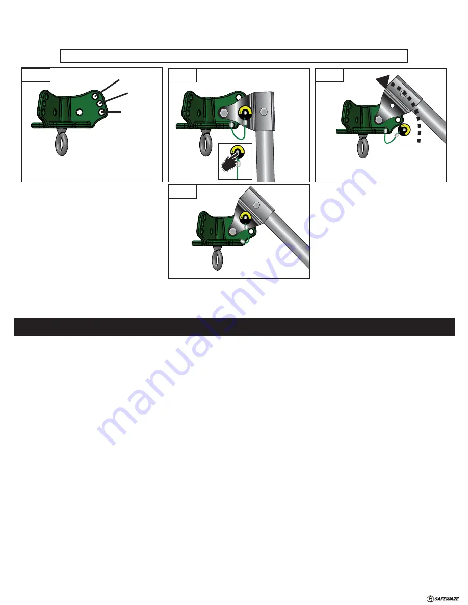
At the Head Unit of the tripod, remove the detent pins and adjust each leg and adjust each leg to their necessary position based on operational
requirements. Reinstall detent pins.
Step 3:
Remove the leg detent pins. Adjust the tripod leg length as needed (stance 2A is the shortest with no extension needed, 2B is the longest) by
depressing the button locks and sliding the inner sections of the tripod legs out until buttons lock and re-engage. Reinstall detent pins.
Step 4:
Prior to standing the tripod into its upright position, it is recommended to install your devices (Section 15). If a height adjustment or installation of
devices is required while in the upright position, there are optional tripod steps available to assist in accessibility.
Step 5:
Connect the tripod legs together using the provided safety chain. Ensure all feet of tripod are secured with the chain to resist moving, splaying, or
shifting from the tripod set location. It may be necessary to configure the two tripod feet towards the nearest edge in a vertical position for best grip.
NOTE:
Safety Chain MUST be installed to complete installation. Remove all slack from chain. Do not use tripod without safety chain installed.
14.2 INSTALLATION AND USE (10’ TECH TRIPOD - OVER EDGE)
The 10’ Tech Tripod is designed for use over an edge. Over edge installations are inherently more complex than a standard tripod configuration. Users must
ensure that adequate anchorage is available for tie-back of the tripod. For edge applications, there must be (2) tie-back anchor locations to secure the tripod.
Each tie-back anchorage must be at least 6x the users weight capacity.
FIGURE 6 - HEAD UNIT/LEG ANGLE ADJUSTMENT FOR 2A and 2B
PUSH
TO
O
PE
N
PU
SH TO OP
EN
Remove
Detent Pin
Head Unit
Hole Pattern
Rotate bracket
to align with
Hole #2
PU
SH TO OPE
N
#1
Collapsed
#2
Dwg 1
Dwg 2
Dwg 3
Dwg 4
Re-install
Detent Pin
PU
SH TO OPE
N
Summary of Contents for 022-11029
Page 19: ...V1 0 2023 Copyright Safewaze...


