background image

Record Menu

The Record Menu contains parameters that control how 
video is recorded.

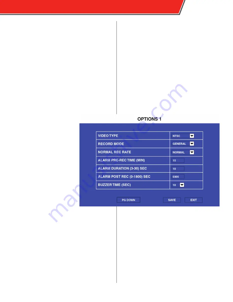
Options (Page 1)

The Options menu contains most of 

the parameters that control how long 

and when the DVR records video.

VIDEO TYPE

: Select NTSC or PAL. 

RECORD MODE

: Select GENERAL 

to began full-time recording 

automatically when the DVR is 

powered on.  Select TIMER to begin 

recording  as defined in the Time 

Record menu.  Select EVENT to record 

only when an event is triggered. 

NORMAL RECORD RATE

: Select 

NORMAL to record video at the 

quality specified in the Record Setting 

menu at all times.  Select 1 FRAME 

to normally record only 1 frame per 

second, until an event is triggered, 

when recording will automatically 

switch to the quality specified in the 

Record Setting menu.  This option is 

useful to conserve storage space. 

RECORD FILE TIME

: Select the duration (15, 30, 45, 60 

minutes) of recording packets. 

ALARM DURATION

: Select the amount of time, from 3 to 30 

seconds, to be recorded and marked as an event. 

ALARM POST REC TIME

: Select the amount of time, up to 

1800 seconds, to be recorded after triggering an event. 

OUTPUT DUR. TIME

:  Select the duration of time (between 

0-240 seconds) that an optional electrical output is sent 

during an alarm.

If an event is trigger while another 

event is being recorded it will be 

considered one event.  The event will 

end after the second trigger and the 

time specified in the ALARM DURATION 

field.

OBSERVER 4000 USER GUIDE

21

Summary of Contents for Observer 4000

Page 1: ...OBSERVER 4000 USER GUIDE...

Page 2: ...implied warranties of merchantability and fitness for a particular purpose Safety Vision shall not be liable for errors contained herein or for incidental or consequential damages in connection with...

Page 3: ...Insertion 6 Remote Control 7 Live View 8 Menu Navigation 8 Video Playback 9 Exporting Video Files 11 Configuration 12 System Menu 12 Record Menu 21 Event Menu 28 Peripheral Menu 36 System Information...

Page 4: ...press it in until it ejects 6 Mirror Secondary SD Card Slot Insert an SD card into the slot until it clicks To remove the SD card briefly press it in until it ejects This SD card can be used for mirr...

Page 5: ...nection for optional RS232 accessories such as a Garmin GPS antenna 4 A V OUT Port Connection for 4000 A VOUT ADA to an external monitor 5 A V IN 1 4 Ports Connection for SV A V INPUTADA to cameras 6...

Page 6: ...Main Wiring Diagram OBSERVER 4000 USER GUIDE 4...

Page 7: ...the DVR to the surface with self tapping screws or rivets Ensure that the front panel of the DVR remains accessible and there is a minimum 2 5 inches of clearance for cables Do not install the DVR in...

Page 8: ...ounter clockwise 2 Release the faceplate latch 3 Open the faceplate Opening the faceplate automatically turns the DVR off 4 Wait until the DVR has completely powered down PWR status LED has turned off...

Page 9: ...e left and right arrow keys can be used to rewind or fast forward Press the Enter key while viewing the live view to display a comprehensive status screen 4 Additional Remote Control Keys VGA Switch t...

Page 10: ...unit number is 0 and the default password is 88888888 For more information on setting the device password navigate to Configuration then System then User Security Use the up and down arrow navigationa...

Page 11: ...ded video for which you want to search The select SEARCH Available video appears on the calendar display Green days indicate normal video was recorded red days indicate event files were recorded Use t...

Page 12: ...NAME Displays the type of event that triggered the video recording DATE Displays the date on which the video was recorded TIME Displays the time the video recording started FIRST PGUP PGDW LAST Use th...

Page 13: ...TO EXPORT USB field in the General menu see page 15 2 Insert a USB thumb drive into the USB port on the front panel of the DVR 3 Press the F1 key on the remote control A message appears to indicate vi...

Page 14: ...DD date formats Time Use the number keys on the remote to set the current time manually FORMAT Select from 12 hour 12H or 24 hour 24H time formats TIME SYNC SOURCE Select Global Positioning System GP...

Page 15: ...lect ON to begin recording automatically upon start up Select OFF to require recording be manually triggered ON OFF TYPE IGNITION SHUT DOWN DELAY MIN Use the number keys on the remote control to manua...

Page 16: ...e remote control to input a unique number ranging from 00000 to 99999 COMPANY NAME Use the arrow keys on the remote control to enter the name of the agency to which the DVR belongs VEHICLE NO Use the...

Page 17: ...control to select a device from the drop down menu Available devices include SD inserted SD card or USB inserted USB flash drive 2 Select OK A Warning message appears 3 Select OK 4 The format process...

Page 18: ...Upgrade menu 6 Ensure FIRMWARE is selected in the drop down menu 7 The MCU update function is not active at this time 8 Select UPGRADE The update process begins The DVR first checks for an appropriate...

Page 19: ...at storage media or export or delete the system log USER may only view video and video logs cannot access configuration menus PASSWORD Enter an eight digit password with the number keys on the remote...

Page 20: ...SET to erase all stored data in the History menu in System Information EXPORT CURRENT SETTINGS To export all of the current settings to a USB flash drive insert one in the front USB port and select EX...

Page 21: ...ile 1 Insert a USB flash drive into the front USB port 2 Select EXPORT SYSTEM LOG The system log is automatically exported to the USB flash drive To delete the user log 1 Select DELETE SYSTEM LOG A re...

Page 22: ...to the DVR s USB port This blackbox file contains metadata on assorted parameters of the DVR 1 Insert a USB flash drive into the DVR s USB port 2 Select the BLACKBOX FILE op tion A prompt appears as t...

Page 23: ...me per second until an event is triggered when recording will automatically switch to the quality specified in the Record Setting menu This option is useful to conserve storage space RECORD FILE TIME...

Page 24: ...ARM PRE REC TIME Select 15 30 45 or 60 minute file packing sizes optional SD CARD TYPE Select INTERNAL RECORD MODE OF STORAGE Select from the following options OFF Disable any recording to the seconda...

Page 25: ...ved to the TOP or BOTTOM of the screen The following information is available to be displayed DATE TIME The date and time of the recording ALARM The trigger that initiated the recording if active ACCE...

Page 26: ...n the live view ENCODE Select CBR for constant bit rate keeps camera bit rate constant regardless of motion but less efficent in using storage space or VBR for variable bit rate varies bit rate depend...

Page 27: ...HD1 704 288 or CIF 354 288 FR Select the frame rate in seconds of this camera Select from 1 to 30 FPS NORMAL QUALITY Select the quality of recording during normal recording with 1 being the best for o...

Page 28: ...m Select the following for each channel ENABLE Select ON to enable this camera for sub streaming Select OFF to disable it RES Select the resolution for this camera when sub streaming Select from CIF o...

Page 29: ...using the number keys on the remote control in the HH MM SS HH MM SS format where the first time is when recording will begin and the second time is when recording will stop All times are in the 24 ho...

Page 30: ...oard and enter an abbreviated or truncated name of the sensor here This name appears in the OSD while reviewing video in Foresight SD SET Select LOW for low to high normally closed NC or select HIGH f...

Page 31: ...channel to displayed in the FULL SCREEN field when that sensor is active Select an individual camera or the 1 4 option which displays a quad view Enter the amount of time channels are displayed in ful...

Page 32: ...alarm type select ON or OFF for outputs 1 and 2 OUT1 and OUT2 Select ON in the SNAP field for each alarm type to produce a jpg snapshot when that alarm is triggered OVERSPEED LOW SPEED HIGH TEMP LOW T...

Page 33: ...isable it THRESHOLD Use the number keys on the remote control to enter the speed at which the event is triggered ALARM Select ON to enable the ALM LED on the front of the DVR when the THRESHOLD speed...

Page 34: ...ding and not shading This is useful when the camera s angle of view covers both areas with frequent motion and monitored areas B D SENSITIVE The blind detection feature senses when a camera s view may...

Page 35: ...LE Select ON to enable voltage protection LOW VOLTAGE Enter the minimum voltage in volts that the DVR can receive before it automatically disconnects from the CMS or shuts down VOLTAGE OF START Enter...

Page 36: ...or each camera When snapshot mode is enabled video is recorded in a series of snap shots taken in a constant interval This may reduce storage usage for some non critical camera views For each camera s...

Page 37: ...o activate the feature Enter the time the operator is authorized to drive continuously before resting in the DRIVING DURATION field in HH MM SS format When a driver exceeds this time based on the DVR...

Page 38: ...that control optional connected peripheral accessories Ext Com Setup The Ext Com Setup menu enables optional connections to the RS232 port MODE Select STANDARD RS232 1 Select NONE or EXT GPS for the...

Page 39: ...tch The Language Switch menu allows you to change the language of the DVR s configuration menus In the CHOOSE LANGUAGE field select English Russian Spanish Polish Portugese or Turkish OBSERVER 4000 US...

Page 40: ...U VERSION The MCU feature is not active at this time DEVICE NAME Displays the name of the storage unit CAPACITY Displays the overall capac ity of the storage unit in gigabytes GB FREE SPACE Displays t...

Page 41: ...iles or kilometers driven LOWEST VOLTAGE IN HISTORY Displays the lowest received voltage including the date and time it was recorded HIGHEST VOLTAGE IN HISTORY Displays the highest received voltage in...

Page 42: ...dules menu displays the status of optional installed modules GPS MODULE Displays NORMAL if a GPS module is installed NONE is one is not GPS SIGNAL Displays if the GPS signal received is valid 40 OBSER...

Page 43: ...ckable 1 Class 10 SD Card 128GB max 1 Class 10 SD Card 128GB max mirror recording Interfaces 1 x RS 232 and 1 x USB 2 0 on front panel lockable Sensor Inputs 4 inputs 2 outputs Power Input 8 36V DC Po...

Page 44: ...Appendix B Dimensions 42 OBSERVER 4000 USER GUIDE...

Page 45: ...this page intentionally left blank OBSERVER 4000 USER GUIDE 43...

Page 46: ...by the customer to damage to products or parts caused by misuse accident improper installation improper maintenance or use in violation of instructions furnished with the product to units that have b...

Page 47: ...ent This equipment generates uses and can radiate radio frequency energy and if not installed and used in accordance with the instruction manual may cause harmful interference in which case the user w...

Page 48: ...opyright 2015 Safety Vision LLC All Rights Reserved CORPORATE HEADQUARTERS 6100 W Sam Houston Pkwy N Houston TX 77041 5113 Main 713 896 6600 Toll Free 800 880 8855 Fax 713 896 6640 www safetyvision co...

Reviews: