background image

Car lift installation, operation and maintenance manual                        Type

4SF-4000B 


SAFETY INSTRUCTIONS


1.1 Statement 

  We will give the user one-year warranty of quality for the machine. If something wrong with the machine within the term of service, we will 

repair  or  replace  the  product  according  to  the  user

s  demand.  The  manufacturer  will  not  take  any  responsibility  for  improper  installation  and 

operation,  overload  running,  wrong  concrete  ground  (that  can  not  meet  the  requirements  in  the  manual),  normal  mechanical  abrasion  and 

insufficient maintenance.


The lifting machine is designed for lifting vehicles and does not allow any other use. Neither the dealers nor we are liable  for the accidents and 

damage caused by the machines for other purposes.. 

Be sure to pay attention to the tonnage mark on the machine and shall not attempt to lift the vehicle beyond the rated lifting weight.


Please  read  the  manual  carefully before  installation  and operation of  the  lifting  machine  so  as  to  avoid  any  loss of property  or  even personal 

injury caused by improper operation.


In the absence of the manufacturer's permission, no user may alter the control and other mechanical parts of the machine without permission.


1.2 Qualified operator and instructions for use


1.2.1 

Professional trained personnel can operate the lift.


1.2.2 

Electrical connections must be operated by personnel with electrical qualifications.


1.2.3 

Laypeople shall not use lifting machines.


1.3


Notes


1.3.1 

Do not install the lift on asphalt. The thickness of the concrete must meet the requirements.


1.3.2

 Before you operate the lift, read and understand the instructions for safety operation carefully.


1.3.3 

Customers do not have special needs customized, lifts are generally not used outdoors.


1.3.4 

Hands and feet away from the lift’s moving parts, when the machine falling, remove the hands and feet, to avoid being hurt.


1.3.5 

Professional trained personnel can operate the lift.


1.3.6 

The operator is not allowed to wear fat clothing so as not to be caught in the moving parts during the lifting of the machine.


1.3.7 

The lifting machine must be kept clean and tidy and should not be piled up so as not to cause accidents.


1.3.8 

Work under the car, make sure the safety of the lift in occlusal state.


1.3.9 

Check the parts for damage at any time, check the synchronism of the machine and the flexibility of the moving parts, and pay attention to 

the regular maintenance. Once the abnormal situation is found, stop using and contact the dealer immediately. 

1.3.10

 Please lowest the machine after operation.


1.3.11

The components of the lift shall not be altered without the manufacturer's permission.


1.3.12 

If the machine is not used for a long time, the user needs


A.Cut-off power

      B.

Emptying hydraulic fluid

     C.

The moving parts are lubricated with hydraulic oil.   


Summary of Contents for 4SF-4000B

Page 1: ...4000Kg INSTALLATION OPERATION AND MAINTENANCE MANUAL The instructions is part of the product Please keep them where you can easily find them as reference Read the instructions carefully before starting installation operation and maintenance The manufacturer and its distributor are not liable for any accidents caused by customer s arbitrary modification of the part or operation ...

Page 2: ... Before installation 3 1 1 Tools and equipments needed 3 1 2 Ground requirement 3 1 3 Check accessories 3 2 Precautions during installation 3 3 Installation steps 3 4 Notes after installation 4 OPERATION 4 1 Operating instructions 4 2 Operation flow chart 4 3 Instructions for use 5 TROUBLE SHOOTING 6 MAINTENANCE 7 ENCLOSURE Enclosure 1 Packing list Enclosure 2 Overall diagram Enclosure 3 Space req...

Page 3: ... 1 2 2 Electrical connections must be operated by personnel with electrical qualifications 1 2 3 Laypeople shall not use lifting machines 1 3 Notes 1 3 1 Do not install the lift on asphalt The thickness of the concrete must meet the requirements 1 3 2 Before you operate the lift read and understand the instructions for safety operation carefully 1 3 3 Customers do not have special needs customized...

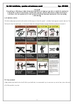
Page 4: ...ot randomly discharge liquid protect the surrounding environment 1 4 WARNING SIGNS All safety warning signs presented on the machine with the purpose to draw the operator s attention from dangerous or unsafe situations The labels must be kept clean and they have to be replaced if detached or damaged Read the meaning of the labels carefully and memorize it 1 5 Noise standard Lifting machine noise s...

Page 5: ... movement process because the steel wire rope traction between bridge decks and beams so as to realize the lift up and down movement and then achieve the purpose of lifting C The insurance agency safety lock block in each process will automatically rise and bite the column within the rack together make sure not because the hydraulic system failure caused by falling D Rolling jack for change the ti...

Page 6: ...driver 11 An one word screwdriver 12 A needle nose pliers 13 Ф17 Ф19 Ф22 Socket wrench each 1 14 Hammer 1 pieces 4 pounds 15 Circlip pliers 1 piece 3 1 2 Ground requirement The car lift must be installed on the concrete ground level strong concrete strength is more than 3000psi the error is less than 5mm the minimum thickness of not less than 300mm in the new pouring concrete need maintenance 20 d...

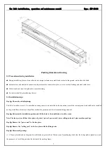
Page 7: ...lled on strong concrete not installed on the expansion joint of the cement ground and shall not be installed on the ground floor of the two or high floor without the permission of the relevant building personnel Step 2 Determine the installation position and lift the hoist to the installation site with a crane Note The four post car lift has three pieces of goods 1 piece of power unit 1 piece roll...

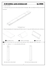
Page 8: ...ve the packing bags take A 2 approach spans B 4 block the tire bracket C 1 spare parts D 2 dashboard and put them in the free space A Approach spans 2 pieces B Block the tire bracket 4 pieces D Dashboard 2 piece 5 Remove the belt and remove the screws from the main and secondary posts and the packing frame Take D 1 main column E 3 sub column F 1 main beam G 1 vice beam and put them in the free spa...

Page 9: ... bridge plate under the package and the packing frame remove the packing frame Take H main bridge plate with the lifting equipment and move to the free space Main bridge plate 1 piece Step 6 Determine the machine installation layout Mark the standing points of the four posts with tape measure and chalk make sure the two diagonals are the same length ...

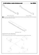
Page 10: ...on wire rope connection and tubing connection B The main and secondary beam is installed before the factory including the connection of the unlocking device the connection of the main safety the connection of the cable break safety and the connection of the rope wheel Step 8 The main secondary beam is connected with the main and sub slab bridge dashboard will connect with the main and sub slab bri...

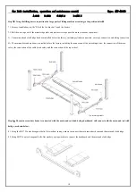
Page 11: ...p and down to push the column into the beam 9 3 Insert the insurance strip into the beam along the inside of the beam end sealing plate 9 4 Using M10 30 semicircular head square neck screw spring washer flat pad nut to fix the bottom of the insurance stri 9 5 Using the M20 flat pad and nut fixed the insurance strip to the top of the column 9 6 Connect the steel cable at both ends of the beam to th...

Page 12: ...Type 4SF 4000B 12 Step 10 Install steel cable limit shaft Step 11 Install top limit switch Step 12 Install power unit and control box Step13 Install four column caps and beam end cover Step 14 Install approach bridge Step 15 Installation of oil pipe joints ...

Page 13: ...nd the machine the Rolling jack with lift device placed on the track of the main and sub bridge plate Four post car lift sub slab bridge plate for the movable type its main purpose is to adjust according to the width of the vehicle to the distance between the main bridge and sub slab bridge to adapt more vehicles repair and maintenance the distance between the main bridge and sub slab bridge is ac...

Page 14: ...s No 32 anti wear hydraulic oil is recommended The viscosity of the hydraulic oil largely determines the lifting speed of the lifter The tank has a capacity of 10L usually only a capacity of 80 Step 19 Connect the power supply Connect the power source and the corresponding electrical components according to the diagram below Step 20 Adjust the level of the lifting machine at four points Please do ...

Page 15: ...g 3 If the plate requires gaskets to ensure the level plug the appropriate quantity of the gasket so that the expansion bolt is tightened and the column and the ground are vertical Plug in the gasket and start tightening the expansion bolts 4 Install the sub column in accordance with steps 1 2 3 Drill hole Dust removal knock expansion pin Wrench tightening Attention 1 The above steps are all the i...

Page 16: ...r will not bear any responsibility for the consequence resulted from the operation above mentioned 4 1 4 The staff or operators shall be in a safe position when the machine lift or lower 4 1 5 When lifting arms are in high position The power must be switched off to avoid misoperation by non operating personnel 4 1 6 When working under the car you must press down handle to make sure the safety lock...

Page 17: ...sition drive away the car 4 5 Instructions for rolling jack TROUBLE SHOOTING Caution If you are unable to resolve the problem please contact the manufacturer for assistance We will be the first to help you solve the problem provide relevant failure messages and picture of failure so that manufacturers can troubleshoot you at the fastest speed Phenomenon Reason Method Lift makes excessive noise Fri...

Page 18: ...aulic oil Cylinder seal abrasion Replace seals The cylinder lubrication is poor Replace the lubricant Slow down The downward throttle is stuck and has obstructions Clean remove or replace The hydraulic oil is dirty Replace hydraulic oil Explosion proof parachute valve has obstruction Replace Explosion proof parachute valve Hydraulic hose has an obstruction Hydraulic hose has an obstruction Steel c...

Page 19: ...heck the safety device as previously described Check hydraulic fluid level as follow let the trolleys go up completely and in case they do not reach maximum height add oil Check the tightness of the expansion bolt Inspection items used when fixing methods 6 3 Monthly maintenance Check the tightening of screws heck the hydraulic system seal and tighten the loose unions if necessary Check the greasi...

Page 20: ...ing 1 Standard configuration spare parts list No Figure No Name Source No Remark 1 Non M16 120 expansion bolt Outsourcing 16 Galvanized 2 XH 6435 2000 17 End shield of cross member Outsourcing 4 3 Non M8 12 soket head cap screw Standard parts 4 Galvanized 4 Non M8 spring washer Standard parts 8 Galvanized 5 Non M8 flat pad Standard parts 8 Galvanized 6 XH 6435 1000 07 Four column column top cap Ou...

Page 21: ...on M6 Spring washer Standard parts 2 Galvanized 28 Non M6 flat washer Standard parts 1 Galvanized 29 Non 1 4 8mm 90 degree fast pipe joint Standard parts 2 30 Non Y type quickly trachea three way connection Standard parts 1 31 Non M4 20 cross cap screw Standard parts 1 Galvanized 32 Non 24V electronic air valve Standard parts 1 33 Non M4 35 cross cap screw Standard parts 1 Galvanized 34 Non M4 nut...

Page 22: ...r lift installation operation and maintenance manual Type 4SF 4000B 22 Enclosure 2 dimensions drawing Enclosure 3 Foundation installation drawing Enclosure 4 Hydraulic principle diagram Four wheel aligner ...

Page 23: ...oading valve 6 Motor 7 Gear pump 8 Flow control valve 9 Filter Enclosure 5 Schematic diagram of electrical equipment SB1 Emergency stop button SB2 Up button SB3 Down button SB4 Lock button KM A C contactor KT Time relay AV Rising limit HL Power supply indicator QF Power switch FU1 Fuse 1 FU2 Fuse 2 TC Transformer Q Electronic valve Y Oil return electromagnet ...

Page 24: ...Car lift installation operation and maintenance manual Type 4SF 4000B 24 ...

Reviews: