JUL 2023 | R1.7
© Safe Fleet | All rights reserved
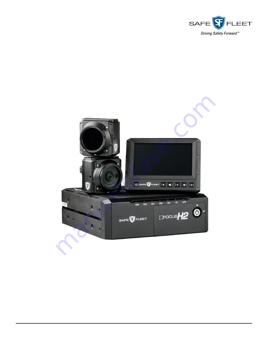
Installation Guide
Document Revision: 1.7
FOCUS H2
In-Car Video System
Page 1: ...JUL 2023 R1 7 Safe Fleet All rights reserved Installation Guide Document Revision 1 7 FOCUS H2 In Car Video System...
Page 2: ...age Contents 3 2 2 Mounting Parts List 4 2 3 Mounting the FOCUS H2 CPU 4 2 4 Mounting the Monitor 6 2 5 Mounting the Front Camera 7 2 6 Mounting the Rear Camera 10 2 7 Wiring the FOCUS H2 11 2 8 Conne...
Page 3: ...y equipment requirements and the placement of existing equipment every installation in a public safety vehicle is unique The information contained herein is subject to change without notice Safe Fleet...
Page 4: ...ts FOCUS H2 CPU P N FOCUS 12 01 Front Camera P N FOCUS 15 06 C 02 Rear Camera P N FOCUS 15 03 U 02 H2 Monitor P N FOCUS 12 02 GPS P N FOCUS 04 14 Power Harness P N FOCUS 04 03 Monitor Extension Cable...
Page 5: ...e two ways to fasten the CPU mounting bracket depending whether a rack is present for installation NOTE CPU Mount CPU mount includes carriage bolts which should be used instead of self drilling screws...
Page 6: ...x 1 4 20 carriage bolts and nuts b If a rack is not present fasten the CPU mounting bracket to the vehicle with 4x 10 self tapping screws CAUTION Be Careful Be careful not to damage the vehicle s fuel...
Page 7: ...s and a split lock washer and secure via the top left hole with a 8 32 screw and 2 flat washers as shown in the figure below 2 Assemble the Swivel mount base and the angle plate with a carriage bolt 2...
Page 8: ...and the flat plate 3 There are 2 operating options for the end user to choose from Pan Tilt option In order for the end user to be able to aim the camera it allows panning and tilting of the camera w...
Page 9: ...mounting positions to choose from depending on the agency s mounting policy b To mount the front camera using the Fixed option i Insert a tooth lock washer and the hanging bracket to the carriage bolt...
Page 10: ...the camera to the bracket and properly position the camera NOTE Upper and Lower Mounting Holes There are upper and lower mounting positions to choose from depending on the agency s mounting policy Up...
Page 11: ...1 Make sure the rear camera is orientated correctly The part number sticker should face up Bolt the camera mount to the rear of the camera using the pan head screw Make sure the camera mount is on the...
Page 12: ...ery 5 Reattach the fuse and fix the fuse holder firmly into place 6 From the power harness run the YELLOW wire along the dash and finally connect it to an ignition source 7 Connect the Power Harness t...
Page 13: ...camera extension cable brown from the front camera location to the CPU 2 Connect the camera pigtail to the camera extension cable 3 Connect the camera extension to the port on the back of the CPU lab...
Page 14: ...ed CAM 2 To connect the extension securely thread up and thread down the connectors at the base of the plugs NOTE Orientation For proper orientation make sure the top flat side of the connector is fac...
Page 15: ...Connector Function Color 1 DI 1 Input Lightbar Black yellow stripe 2 DI 2 Input Brake Black white stripe 3 DI 3 Input Spare Recommended Door Black blue stripe 4 DI 4 Input Spare Recommended Gun Lock...
Page 16: ...t labeled GPS 4 Insert the USB connector in to this port 2 8 2 Connecting the Wireless Microphone Overview of the Wireless Microphone The H2 In car video system supports up to two wireless microphones...
Page 17: ...ttery antenna and power adapter from the packaging 2 Unscrew the lid of the battery compartment and fit the battery inside 3 Carefully fix the lid on to the battery compartment 4 Thread the antenna in...
Page 18: ...eiver s register contacts A confirmation tone sounds indicating the receiver and microphone have synchronized frequencies The microphone is now in Standby mode and ready for use 4 If necessary repeat...
Page 19: ...from any other antenna or the light bar This antenna operates on the line of sight concept and needs a clear path to locate the access point The low loss cable should be routed as far away from any h...
Page 20: ...it was connected and calibrated to a FOCUS H2 device 1 Upon first bootup the following calibration screen will pop up on the LCD Tap the calibration targets center of the red crosshair as precisely a...
Page 21: ...f the FOCUS H2 CPU LED indicators LED Indicators Color Status PWR Amber System powered ON HDD Green Hard drive activity REC Red Recording STBY Green System is ready to power ON IGN Blue Ignition ON CB...
Page 22: ...ide p 21 Service Support Documentation and Warranty Additional copies of this guide along with other documentation and product warranty can be found on the Safe Fleet Community website https community...