8.2 Mounting the brake calliper to the
carrier (carrier not removed)
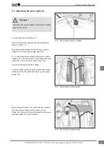
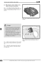
8.2.1 The replacement brake calliper for the
brake can be located with the SAF-HOLLAND order
number on the type plate (see Chap. 1.2) - see
arrow X.
• The guide bushings (4) and (5) and socket
cap screws (39) and (40) are highly stressed
components. They must be replaced with
new parts as soon as the brake calliper (1) is
removed from the carrier (2)!
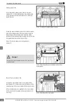
• Hold the brake calliper (1) on the outside only,
never place the fingers between the brake
calliper (1) and carrier (2)! Never attach a
hoisting device to the pad retainer (11) as this
can damage the pad retainer.
Danger !
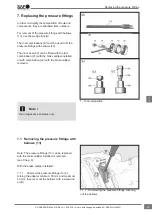
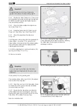
8.2.2 Slide the guide bushings (4, 5) from outside
in the direction of the pad shaft into the guide bear-
ing.
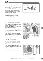
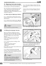
8.2.3 Check the correct seating of the inner bel-
lows (9) and the rings (58) on the guide bushings
(4, 5) (see Fig.).
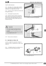
8.2.1 - 8.2.2 - Observe the type plate and remove
the tape
8.2.4 - Checking the inner bellows and ring on the
guide bushing (only fixed bearing side shown in
image)
Removing and installing the brake calliper
36
en
XL-SA40001RM-en-DE Rev A • 02.2016 • Errors and changes excluded © SAF-HOLLAND


