SAF-HOLLAND FleetMaster LowLube Series Installation, Operation, Maintenance & Warranty Information Download Page 20

20

XL-FW503 Rev B

MANUAL SLIDING SECONDARY LOCK

Rebuilding Instructions

If your fifth wheel is equipped with the
manual sliding secondary lock, then
rebuild per standard FleetMaster
Rebuilding Instructions (XL-FW355-XX),
but replace the Manual Secondary Lock
Installation (as stated on Page 7 of 
XL-FW355-XX) with the following:

Note:

During assembly, use threadlocker

(Permalok MM118, Loctite No. 243, or

equivalent on all threads.

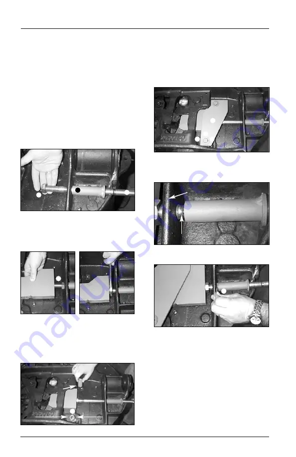
1. Insert handle through guide sub-

assembly and install jam nut on

handle rod (

Figure 3 – Items 1, 2 & 11

).

2. Screw handle into threaded safety

bar making sure handle grip is

oriented towards ramps of wheel and

tighten jam nut (

Figure 4 & Figure 5

)

(

Item 3

).

3. Position spacer tubes over threaded

holes in casting. These spacers come

in two different lengths, so be sure to

place shorter spaced on the raised

portion of casting (

Figure 6

) (

Items 4

& 5

).

4. Position cover on spacers and use

two 1/2˝ washer, two 1/2˝ lock

washer, and two 1/2˝ x 2-3/4˝ bolts,

to fasten cover to casting (

Figure 7

)

(

Items 6, 7, 8, & 9

). Tighten fasteners.

5. Pull secondary lock handle out so

that detent on handle is between

casting rib and guide tube (

Figure 8

).

6. Install spring clip on handle (

Figure

9

) (

Item 10

).

7. Check the manual sliding secondary

lock for proper operation by

pulling/pushing handle to engage

secondary locking bar. Handle

should engage detent when

secondary locking bar is behind

primary lock and also engage detent

when pulled out to allow

uncoupling.

Figure 4

Figure 5

Figure 6

Figure 7

Figure 8

Figure 9

Detent

Raised
Portion

Long Spacer

Short Spacer

Rib

Figure 3

11

Summary of Contents for FleetMaster LowLube Series

Page 1: ...er LowLube Series Fifth Wheels with Manual Sliding Secondary Lock XA 201 S10217 XA 201 S10579 XA 231 S10217 Installation Operation Maintenance Procedures and Comprehensive Warranty OWNER S MANUAL Ques...

Page 2: ...rea Clean Cluttered areas and benches invite accidents 2 Keep fingers away from all potential pinch points in the fifth wheel 3 All fifth wheel maintenance must be performed by a qualified service tec...

Page 3: ...1 2 but not closer than 1 of the cut fore and aft 10 The mounting angle should have a minimum thickness as shown in Chart 1 and should be steel specification ASTM A 36 11 When initially positioning t...

Page 4: ...en in FIGURES 1A 1B and 1C The following sequence is suggested for both fabricated and cast brackets A Securely position the mounting angle to the tractor frame B Bolt the angles to the tractor as sho...

Page 5: ...eg size The fifth wheel top plate and support bracket may be removed from the base plate for ease of handling FIFTH WHEEL SUPPORT BRACKET FLAT MOUNTING PLATE See Chart 1 for minimum thickness INBOARD...

Page 6: ...ng angles to the tractor using recommendations in General Recommendations and in FIGURE 4 6 Reassemble the fifth wheel top plate and bracket sub assembly to the slider base plate if they were removed...

Page 7: ...l assembly carefully review the General Safety Information section on page 2 Installation of Slide Stops 1 It is the responsibility of the installer to insure that slide stops are installed properly a...

Page 8: ...eps were properly followed and that all components removed to facilitate installation are reinstalled 2 Check the fifth wheel locking mechanism with a Holland TF TLN 5001 2 or TF TLN 1500 3 1 2 Lock T...

Page 9: ...n 3 Inspect the lock jsw if it appears dry apply greawse to lock jaw and front of throat directly or throught the lube tube grease fitting located near the front leftside of the fifth wheel 4 Tilt the...

Page 10: ...re are no sharp edges or abrupt changes in elevation 6 The upper coupler should extend adequately rearward to maintain full contact with the fifth wheel during tight turning If it does not at a minimu...

Page 11: ...and back up straight 3 Back the tractor close to the trailer and STOP 4 Chock trailer wheels 5 Connect brake lines and light cord 6 Support slack in lines to prevent interference 7 Set trailer brakes...

Page 12: ...shown below 11 Visual inspection Get out of the tractor Visually check that the lock is closed If you do not obtain a proper couple repeat the coupling sequence Do not use any fifth wheel that fails...

Page 13: ...line clean 9 If equipped pull secondary lock handle and hook on casting located on left road side of fifth wheel 10 Pull primary release handle 11 Release tractor brakes and slowly drive away from tr...

Page 14: ...owly drive the tractor forward or backward to position the fifth wheel 6 Re engage the slide locking plungers Verify that both plungers have fully engaged NOTE Retract landing gear if lowered UNLOCK L...

Page 15: ...le See Step 5 Bracket pocket fittings right and left sides Swing lock to cam arm contact area Recommended Greases A low temp grade recommended for 30 F or lower such as Cato Oil Grease 5213 Craftsman...

Page 16: ...ughly clean the fifth wheel locking mechanism every 6 months or 60 000 miles and relubricate see Figure 1 on page 15 Re check operation with TF TLN 5001 Lock Adjustment Tool 3 Inspect the fifth wheel...

Page 17: ...eel resistance against the lock adjustment tool Once you begin to feel resistance STOP At this point the fifth wheel is OVERADJUSTED and NOT useable Using an improperly adjusted fifth wheel could resu...

Page 18: ...a plunger is binding on the plunger pocket remove the plunger using a Holland TF TLN 2500 spring compressor Grind the top edges of the plunger 1 16 as shown Re install and adjust the plungers as expl...

Page 19: ...34 F Nut Jam 3 4 16 3 XA 10216 Bar Tertiary Locking 4 XA 10213 2 Spacer Cover Plate 5 XA 10213 1 Spacer Cover Plate 6 XA 10212 Plate Cover Item Part No Description 7 XB T 49 Washer 1 2 8 XB T 45 1 Lo...

Page 20: ...n spacer tubes over threaded holes in casting These spacers come in two different lengths so be sure to place shorter spaced on the raised portion of casting Figure 6 Items 4 5 4 Position cover on spa...

Page 21: ...XL FW503 Rev B 21...

Page 22: ...22 XL FW503 Rev B...

Page 23: ...tion we will cover the cost to repair or replace the product or part We will provide a reasonable labor allowance for removal and repair or replacement and will provide you with parts or reimburse you...

Page 24: ...fore using Failure to open locks can result in damage to the pin TO OPEN LOCKS Slide the handle forward and pull it out to the maximum extension The lock will swing to the open position CAUTION OPEN C...

Reviews: