


9
XL-AS11406OM-en-US Rev E · 2018-04-17 · Amendments and Errors Reserved · © SAF-HOLLAND, Inc., SAF-HOLLAND, HOLLAND, SAF,
and logos are trademarks of SAF-HOLLAND S.A., SAF-HOLLAND GmbH, and SAF-HOLLAND, Inc.
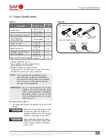
Welding Standards
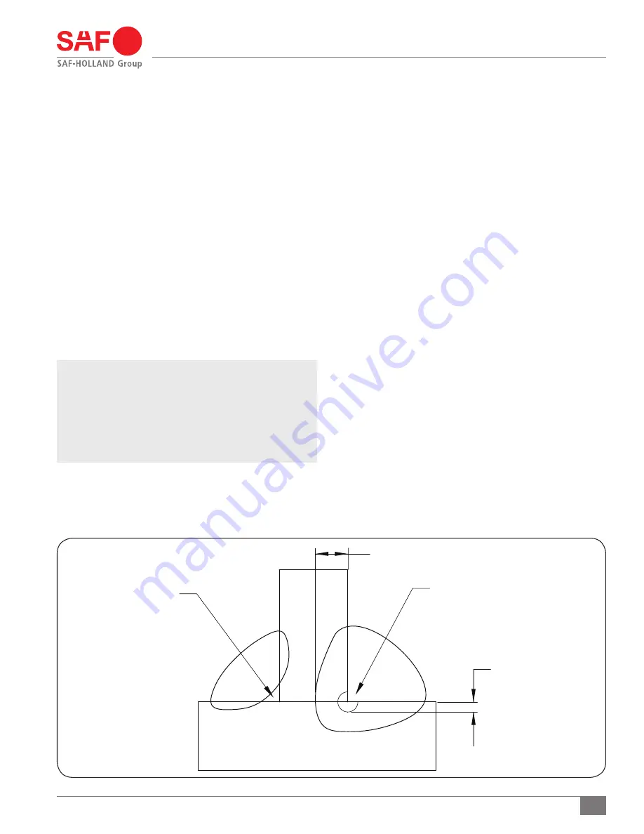
Figure 12
LACK OF FUSION OF
ANY KIND IN THIS AREA
IS NOT ACCEPTABLE AT
ANY TIME
PENETRATION AS MEASURED
THROUGH SEAM
TARGET PENETRATION TO BE
10% OF THINNEST MATERIAL
FROM INTERSECTION OF FILLET
AS ILLUSTRATED
TARGET PENETRATION
9. Welding Standards
9.1 Scope
When welding is required for the suspension repairs, observe
the requirements below. This specification applies to all
components supplied by SAF-HOLLAND, and its products.
The customer assumes all responsibility for weld integrity if
weld material and procedure differ from those listed below.
9.2 Workmanship
All welding on SAF-HOLLAND products MUST be performed by
a welder qualified according to the appropriate AWS standard
for the weld being made or an equivalent standard. It is the
responsibility of the customer to provide good workmanship
when welding on SAF-HOLLAND products.
9.3 Material
Items to be welded that are made from low carbon or high-strength
alloy steel are to be welded with AWS filler metal specification
AWS A5.18, filler metal classification ER-70S-3, ER-70S-6 or
equivalent unless specified on the installation drawing.
NOTE:
Any substitution for filler material from the above
standard must comply, as a minimum, with the
following mechanical properties:
Tensile Strength - 72k psi (496 MPa)
Yield Strength - 60k psi (414 MPa)
Charpy V Notch - 20 ft.-lbs. (27 N•m) at 0
o
F (-17.7
o
C)
% Elongation - 22%
The recommended welding gas for gas metal arc welding
(GMAW) is 90% Argon / 10% CO2. If a different gas is used,
welds must comply with penetration requirements illustrated
(Figure 12)
. Where the installation drawing specifies
different than above, the drawing shall prevail.
9.4 Procedures
Tack welds used for positioning components are to be
located in the center of the final weld, where practical. Tack
weld should be completely fused to the finish weld. DO NOT
break arc at the end of the weld. Back up all finish welds
at least 1/2" (12.7 mm) or a sufficient amount to prevent
craters at the end of the weld. Where weld is illustrated to go
around corners, it is assumed the corner represents a stress
concentration area. DO NOT start or stop weld within 1" (25.4 mm)
of the corner. Particular care should be taken to prevent
undercutting in this area.
9.5 Weld Size
If weld size is NOT specified, the effective throat of the weld
MUST be no smaller than the thinnest material being welded
(Figure 12)
.
Summary of Contents for CBX-14
Page 2: ......