DS EUROPE
by S2Tech
T R A N S D U C E R S A N D I N D U S T R I A L E L E C T R O N I C S
MICROPROCESSOR
PANEL METER
SERIE
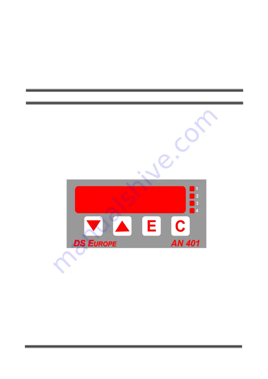
AN-401plus
Version 2 Rev. 12
25/10/2012
TECHNICAL
MANUAL
Page 1: ...DS EUROPE by S2Tech T R A N S D U C E R S A N D I N D U S T R I A L E L E C T R O N I C S MICROPROCESSOR PANEL METER SERIE AN 401plus Version 2 Rev 12 25 10 2012 TECHNICAL MANUAL...
Page 2: ...e 2 7 Page 13 RS485 connections 2 15 with serial connection default table Page 21 DAC settings flow chart Page 22 Modbus baud rate Z Manuali Pitagora AN401 Pitagora UK AN401plus_uk_V2r12_251012 doc No...
Page 3: ...to transducers or other equipment are only parts of more complex systems and plants they are sold in thousands per year for the most different applications which shall meet as many different norms tha...
Page 4: ...20 mA O3 option and 0 20 mA O4 option output cards 8 2 9 Connection of I O card D0 option 8 2 10 Connection of I O card D1 option 9 2 11 Connection to external Inputs 10 2 12 Earth connection CE norms...
Page 5: ...50141 EN 61000 4 4 EN 61000 4 2 EN 61000 4 8 ENV 50204 Manufacturer DS Europe srl Address via F Russoli 6 Milan Italy Equipment type Indicator Conditioner Model AN401 series Year of registered mark 2...
Page 6: ...Power Supply polarity free EARTH Earth Connection 2 2 1 Power Supply From 10 to 35 Vdc From 9 a 15 Vac The power supply generator has to be in position to supply up to 10 W Please use the EARTH conne...
Page 7: ...ansducer s signal input GREEN 5 Power supply to transducer 5 Vdc power supply transducers has to be powered with the power supply voltage generated by AN401plus BLACK 6 Power supply to transducer RED...
Page 8: ...0 20 mA O4 option output cards 2 9 Connection of I O card D0 option Relays electrical characteristics Maximum voltage 30 Vdc Maximum current 2 A Maximum power 1W Operate time from 2 to 15 mS Fig 10 Co...
Page 9: ...terminal 5 AN401 plus slot A or B These AN401 plus outputs are internally protected against polarity reversal with protection diodes 1 2 3 4 5 6 Slot A o B OUTPUT INTERFACE AN 401 PLUS RELAY DPDT I m...
Page 10: ...s electrical characteristics Insulation 200 V peak Settling time from 18 S to 10 mSec Release time from 18 S to 10 mSec 2 12 Earth connection CE norms In order to obtain the maximum immunity to elect...
Page 11: ...RX TX GND GND Most common connection to be used to connect RS 232 connection between AN401plus and PC compatible computers are serial straight cable AN 401 Plus RS 232 Computer Female 9 pin connector...
Page 12: ...AN401plus has no internal resistance for RS485 or RS422 but It can be applied under customer s request This resistor has to be 120 Ohm Watt This resistance is to be applied solely on the last AN401pl...
Page 13: ...Preliminary manual AN 401 Plus V2 r12 25 10 12 13 20 4 Operating parameter setting...
Page 14: ...setting Note valid only if an analog output card is installed into AN401plus Analog output card is active for all operating modes DMODE command allows setting analog output in the following ways DMODE...
Page 15: ...erial connection setting BAUD set value Serial data transmission rate baud Default values Serial data transmission rate baud 0 600 Baud rate 4 9600 baud 1 1200 Address 0 2 2400 Com 0 3 4800 4 9600 5 1...
Page 16: ...999 HIS3 Level 3 hysteresis 0 from 0 to 50 SET3 Level 3 configuration 0 See SET parameter SET parameter Working MODE Function 0 Relay disabled 1 Relay activates on GROSS measurement 2 Relay activates...
Page 17: ...panel see chapter 2 10 7 2 Hold Hold function freezes the measurement actually shown on the display until it is disabled All function measurements are freezed and it is activated by closing KEY 2 con...
Page 18: ...r A Z ID can also be the character if a message is to be sent to an instrument the identifier of which is unknown R read measure command Index 1 digits numeric index indicating to AN401plus which meas...
Page 19: ...ure performed by AN401plus and its value is ranging from 0 to 65535 when maximum is reached It restarts from zero Working of r command is like R command same command structure Example To request measu...
Page 20: ...ries and whatever else not covered by semiconductor Manufacturers warranty The Buyer shall check the delivered Product within 10 days from receipt after this limit the Product shall be considered acce...